DSE Model 560 Automatic Start Engine Management and Instrumentation System Operators Manual
560 OPERATING MANUAL ISSUE 5 4/4/02 MR 21
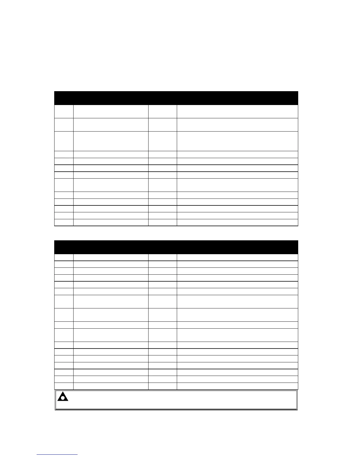
5. ELECTRICAL CONNECTIONS
Connections to the Module are via plug and sockets.
5.1 CONNECTION DETAILS
The following describes the connections and recommended cable sizes to the 3 (or 4) plugs and
sockets on the rear of the Module. See rear panel layout
FIG 5.
PLUG “A” 13 WAY
PIN
No
DESCRIPTION CABLE
SIZE
NOTES
1 DC Plant Supply Input
(-ve)
2.5mm
2 DC Plant Supply Input
(+ve)
2.5mm (Recommended Maximum Fuse 21A)
3 Emergency Stop Input 2.5mm Plant Supply +ve. Also supplies fuel & start
outputs.
(Recommended Maximum Fuse 32A)
4 Fuel relay Output 2.5mm Plant Supply +ve from pin 3. 16 Amp rated.
5 Start relay Output 2.5mm Plant Supply +ve from pin 3. 16 Amp rated.
6 Auxiliary Output relay 1 1.0mm Plant Supply +ve. 5 Amp rated.
7 Auxiliary Output relay 2 1.0mm Plant Supply +ve. 5 Amp rated.
8 Charge Fail Input/
Excitation Output
1.0mm Must NOT be connected to plant supply -ve.
9 Auxiliary Input 1 0.5mm Switch to -ve
10 Auxiliary Input 2 0.5mm Switch to -ve
11 Auxiliary Input 3 0.5mm Switch to -ve
12 Auxiliary Input 4 0.5mm Switch to -ve
13 Auxiliary Input 5 0.5mm Switch to -ve
PLUG “B” 17 WAY
PIN
No
DESCRIPTION CABLE
SIZE
NOTES
14 Not Used Spare
15 Not Used Spare
16 Not Used Spare
17 Not Used Spare
18 Auxiliary Output relay 3 1.0mm Plant Supply +ve. 5 Amp rated.
19 Not Used Spare
20 Magnetic Pickup Input
(+ve)
0.5mm Connect to Magnetic Pickup device
21 Magnetic Pickup Input
(-ve)
0.5mm Connect to Magnetic Pickup device
22 Oil Pressure Input 0.5mm Connect to Oil pressure sender
23 Coolant Temperature
Input
0.5mm Connect to Coolant Temperature sender
24 Sender Common Return 0.5mm Return feed for senders*.
25 CT secondary for L1 2.5mm Connect to secondary of L1 monitoring CT
26 CT secondary for L2 2.5mm Connect to secondary of L2 monitoring CT
27 CT secondary for L3 2.5mm Connect to secondary of L3 monitoring CT
28 Not Used Spare
29 CT secondary common 2.5mm Connect to secondary of all monitoring CT’s
30 Functional Earth 2.5mm Connect to a good clean earth point
NOTE*:- If using single terminal senders refer to connection diagram. If using earth
return type senders connect return terminals to pin 24 and earth pin 24.