DSE Model 560 Automatic Start Engine Management and Instrumentation System Operators Manual
560 OPERATING MANUAL ISSUE 5 4/4/02 MR
28
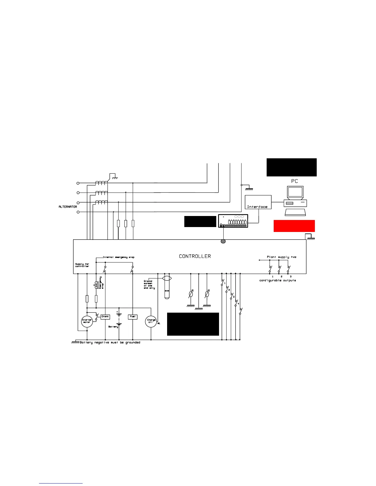
9. TYPICAL WIRING DIAGRAM (3PHASE 4WIRE)
F
F F
F F
LOAD
808
Configuration
Oil
Sender Sender
Temp
5
Configurable inputs
FCC68 - 4 Way
12
3
4
5
6
7
8
910111213
18
20 21 22 23
24
29
25 26 27
31
30
323334
L1
L2
L3
N
MPU
This Ground connection must be
be a sound electrical connection
to the sender bodies.
be used to provide a ground
connection to any other device
on the engine block and must
The wire to Terminal 24 must not
Safety Earth Connection
Must be connected to
the Safety Earth
Optional 157 Relay
Expansion Board
NOTE:-
When connected to a
completed Panel / Gen-set
Real-time diagnostic display
is available