DSE Model 560 Automatic Start Engine Management and Instrumentation System Operators Manual
560 OPERATING MANUAL ISSUE 5 4/4/02 MR
24
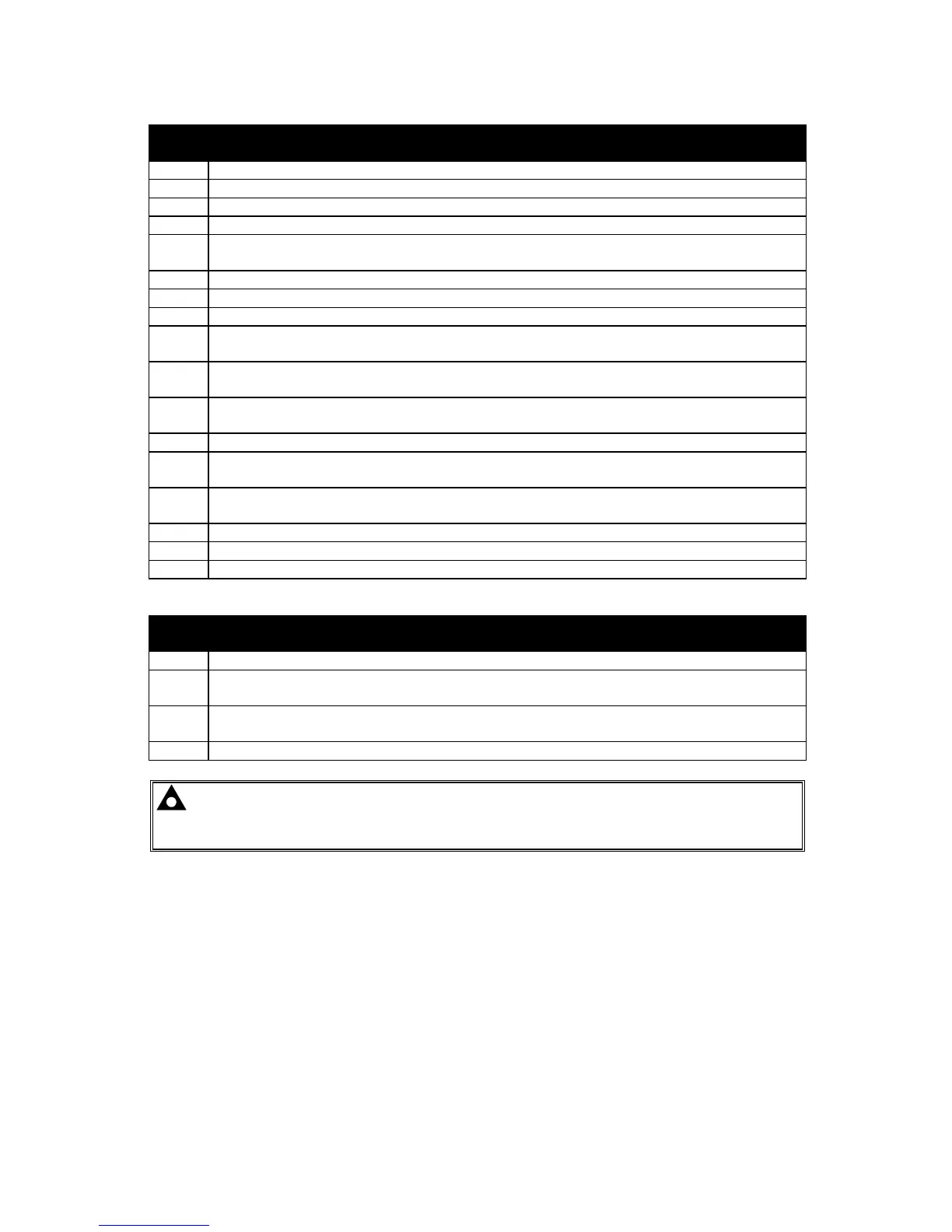
PLUG “B” 17 WAY
PIN
No
DESCRIPTION
14 DO NOT USE
15 DO NOT USE
16 DO NOT USE
17 DO NOT USE
18 Auxiliary Relay output 3. Plant Supply +ve. Configurable output, see Calibration
Manual for options available.
19 DO NOT USE
20 Magnetic Input +ve. An AC signal from the magnetic pickup +ve for speed sensing.
21 Magnetic Input -ve. An AC signal from the magnetic pickup -ve for speed sensing.
22 Oil Pressure sensing input. Connect to resistive type oil pressure sender. Refer to
connection diagram for details.
23 Coolant Temperature sensing input. Connect to resistive type coolant temperature
sender. Refer to connection diagram for details.
24 Sender Common connection. Return feed from sender units - refer to connection
diagram for details.
25 Generator L1 current transformer connection.
26 Generator L2 current transformer connection. If single phase is used do not
connect this pin.
27 Generator L3 current transformer connection. If single phase is used do not
connect this pin.
28 DO NOT USE
29 Generator current transformer common connection and CT earth connection.
30 Functional Earth - Ensure connection to a good clean earth point.
PLUG “C” 4 WAY
PIN
No
DESCRIPTION
31 Generator L1 sensing input. Connect to alternator L1 output.
32 Generator L2 sensing input. Connect to alternator L2 output. If using single phase
only do not connect this terminal.
33 Generator L3 sensing input. Connect to alternator L3 output. If using single phase
only do not connect this terminal.
34 Generator N sensing input. Connect to alternator N output.
NOTE:- A version of the module is available which allows connection to a 3 phase 3
wire system with no neutral (Delta). If using such a module then no connection should be
made to terminal 34. Check the serial number label if in doubt.