DSE Model 560 Automatic Start Engine Management and Instrumentation System Operators Manual
560 OPERATING MANUAL ISSUE 5 4/4/02 MR 15
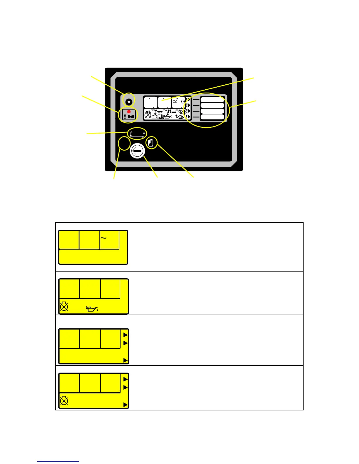
3. DECRIPTION OF CONTROLS
The following section details the function and meaning of the various controls on the module.
O
AUTO
o
F
o
CRPMPSI
88 88 88 88 88 88
AV
L3
BAR
L1 L2 L2 N L1N L3 N
Hz
A
V
V
Deep Sea Electronics plc
Model 560
Scroll Button
Auto Mode
Manual Mode
Stop/Reset
Common Alarm Indicator
User Configurable LCD
Indications with text insert pocket
LCD Display
Selector Switch
FIG2
3.1 TYPICAL LCD DISPLAY SCREENS
INSTRUMENTS
4
1
7. 3 40
9
.
6
3
9
9
.
7
L1- L2 L2- L3 L3- L1
V
(phase to phase AC volts)
The LCD displays the various engine parameters such as ‘ENGINE
SPEED’
, ‘OIL PRESSURE’, ‘HOURS RUN’, etc.
Each instrument is displayed with the appropriate units of measure.
ALARM ICONS
PSI
0.0 0.0
BAR
The LCD also displays the exact nature of any alarm condition
which have occurred such as
LOW OIL PRESSURE using
appropriate icons. This allows very specific alarm conditions to be
brought to the operators’ attention. Refer to the ‘Protections’
section of this manual for details of the alarms.
USER DEFINED
INDICATIONS
The LCD displays the user defined indications when configured and
active. The icons will illuminate and point to the appropriate text
insert label. These indications can be used to indicate the
operation of external equipment (i.e. ‘Battery Charger On’, ‘Breaker
Closed’ etc) or to indicate internal states (i.e. Engine Running,
Safety On, etc).
USER DEFINED ALARMS
!
!
The LCD displays the user defined alarms when configured and
active. The icons will illuminate and point to the appropriate text
insert label. These alarms can be used to indicate the operation of
external alarms (i.e. ‘Low Fuel Level’, ‘Low Coolant level’ etc) or to
indicate internal alarms (i.e. Fail to Stop, MPU fault, etc).