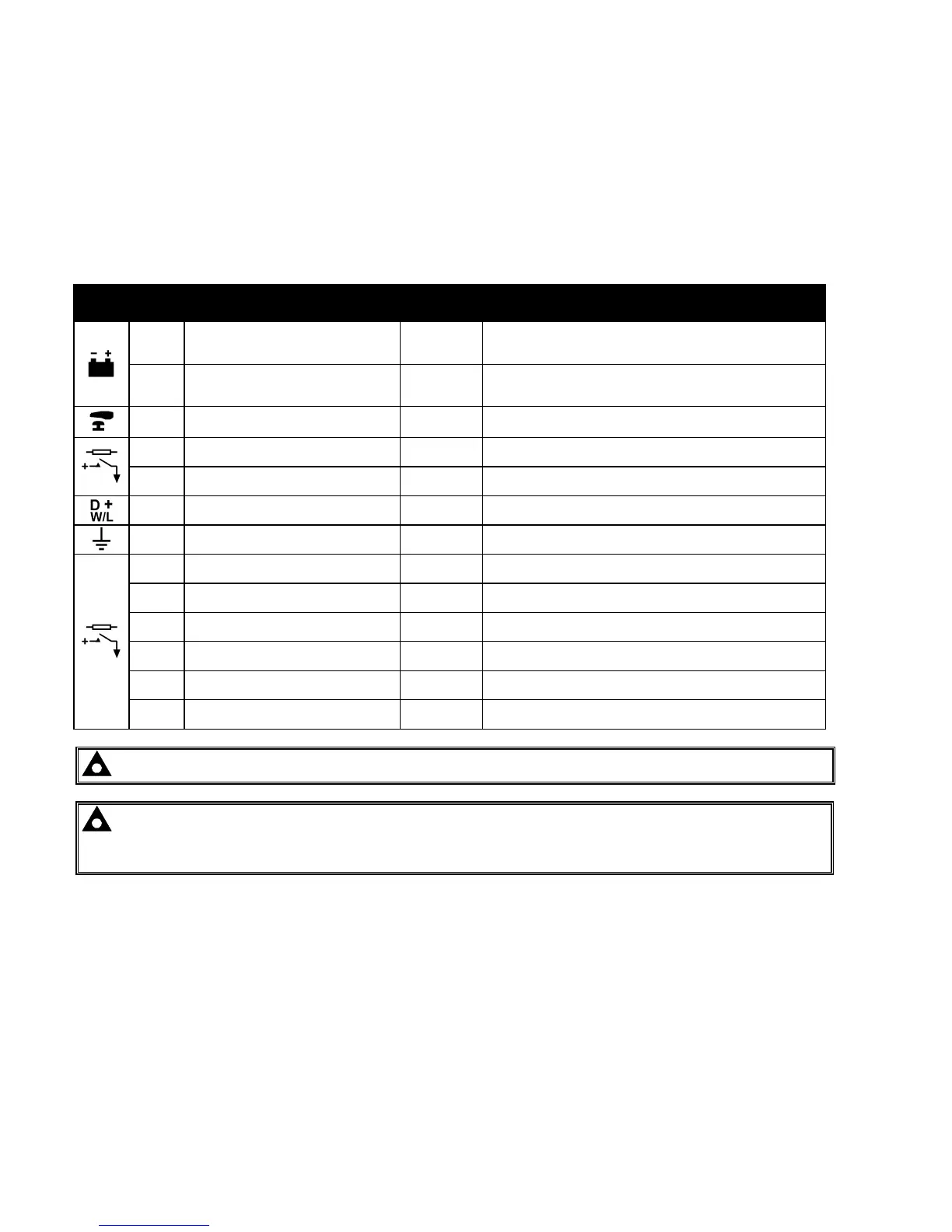
Installation – Terminal Description
38
4 INSTALLATION
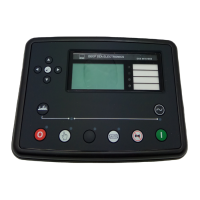
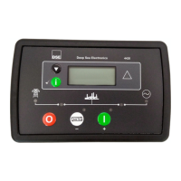
The DSE8600 Series module is designed to be mounted on the panel fascia. For dimension and mounting details,
see the section entitled Specification, Dimension and mounting elsewhere in this document.
4.1 TERMINAL DESCRIPTION
4.1.1 DC SUPPLY, FUEL AND START OUTPUTS
Icon PIN
No
DESCRIPTION CABLE
SIZE
NOTES
1
DC Plant Supply Input
(Negative)
2.5mm²
AWG 13
2
DC Plant Supply Input
(Positive)
2.5 mm²
AWG 13
(Recommended Maximum Fuse 15A anti-surge)
Supplies the module (2A anti-surge requirement) and Output
relays E - K
3 Emergency Stop Input
2.5mm²
AWG 13
Plant Supply Positive. In addition, supplies outputs 1 & 2.
(Recommended Maximum Fuse 20A)
4 Output relay A (FUEL)
2.5mm²
AWG 13
Plant Supply Positive from terminal 3. 15 Amp rated.
Fixed as FUEL relay if electronic engine is not configured.
5 Output relay B (START)
2.5mm²
AWG 13
Plant Supply Positive from terminal 3. 15 Amp rated.
Fixed as START relay if electronic engine is not configured.
6 Charge fail / excite
2.5mm²
AWG 13
Do not connect to ground (battery negative).
If charge alternator is not fitted, leave this terminal disconnected.
7 Functional Earth
2.5mm²
AWG 13
Connect to a good clean earth point.
8 Output relay E
1.0mm²
AWG 18
Plant Supply Positive from terminal 2. 3 Amp rated.
9 Output relay F
1.0mm²
AWG 18
Plant Supply Positive from terminal 2. 3 Amp rated.
10 Output relay G
1.0mm²
AWG 18
Plant Supply Positive. from terminal 2. 3 Amp rated.
11 Output relay H
1.0mm²
AWG 18
Plant Supply Positive from terminal 2. 3 Amp rated.
12 Output relay I
1.0mm²
AWG 18
Plant Supply Positive from terminal 2. 3 Amp rated.
13 Output relay J
1.0mm²
AWG 18
Plant Supply Positive from terminal 2. 3 Amp rated.
NOTE:- Terminal 14 is not fitted to the DSE8600 series controller.
NOTE:- When the module is configured for operation with an electronic engine, FUEL and START
output requirements may be different. Refer to Electronic Engines and DSE Wiring for further information.
DSE Part No. 057-004.