Installation – Terminal Description
41
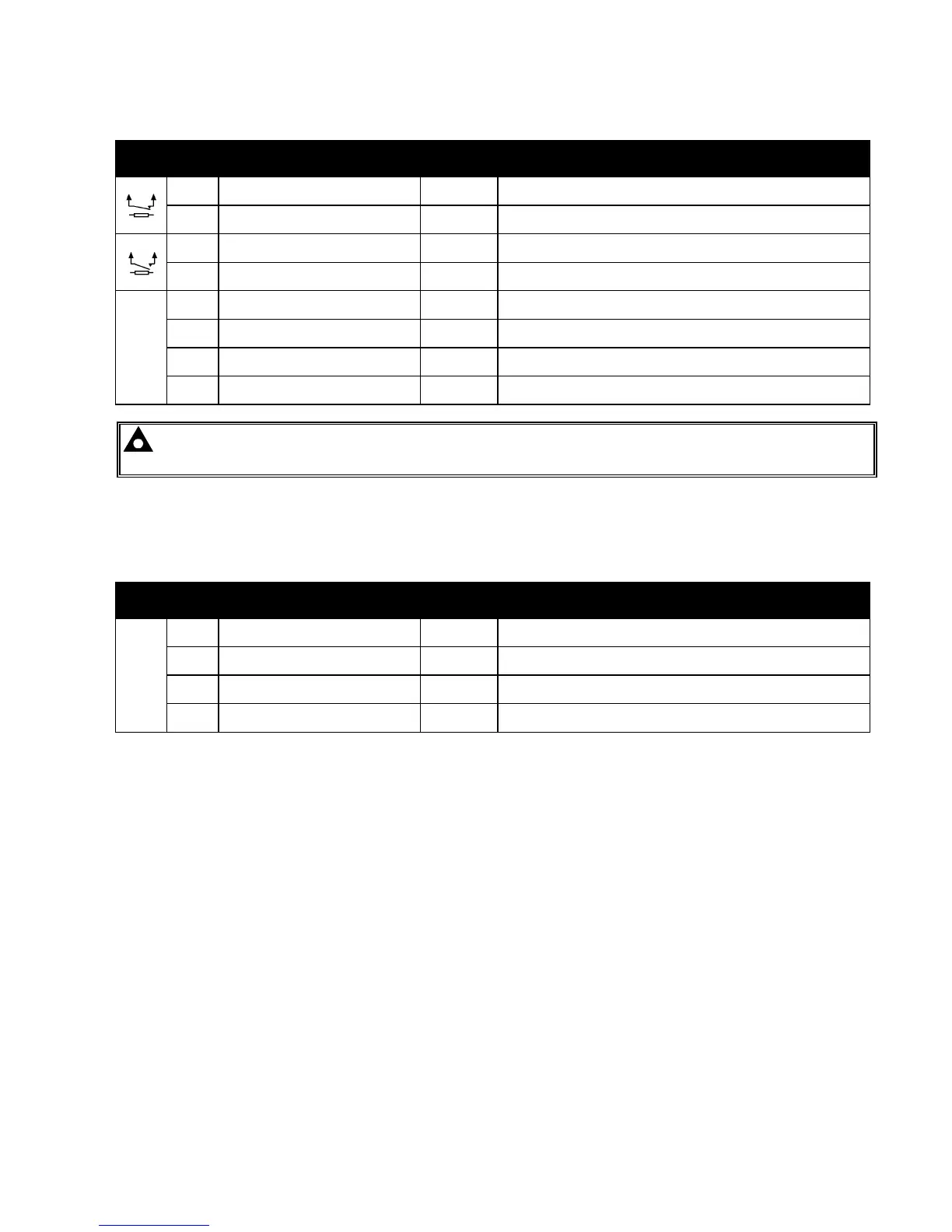
4.1.4 LOAD SWITCHING AND GENERATOR VOLTAGE SENSING
PIN
No
DESCRIPTION CABLE
SIZE
NOTES
39 Output relay C
1.0mm
AWG 18
Normally configured to control load switching device
(Recommend 10A fuse)
40 Output relay C
1.0mm
AWG 18
Normally configured to control load switching device
41 Output relay D
1.0mm
AWG 18
Normally configured to control load switching device
(Recommend 10A fuse)
42 Output relay D
1.0mm
AWG 18
Normally configured to control load switching device
V1
43 Generator L1 (U) voltage monitoring
1.0mm²
AWG 18
Connect to generator L1 (U) output (AC)
(Recommend 2A fuse)
44
Generator L2 (V) voltage monitoring
input
1.0mm²
AWG 18
Connect to generator L2 (V) output (AC)
(Recommend 2A fuse)
45
Generator L3 (W) voltage monitoring
input
1.0mm²
AWG 18
Connect to generator L3 (W) output (AC)
(Recommend 2A fuse)
46 Generator Neutral (N) input
1.0mm²
AWG 18
Connect to generator Neutral terminal (AC)
NOTE: - The above table describes connections to a three phase, four wire alternator. For alternative
wiring topologies, please see the ALTERNATIVE AC TOPOLOGIES section of this manual.
4.1.5 BUS SENSING
These connections are to the common bus supply of the generator system.
PIN
No
DESCRIPTION CABLE
SIZE
NOTES
V2
47 Bus L1 (R) voltage monitoring
1.0mm
AWG 18
Connect to Bus L1 (R) incoming supply (AC)
(Recommend 2A fuse)
48 Bus L2 (S) voltage monitoring
1.0mm
AWG 18
Connect to Bus L1 (S) incoming supply (AC)
(Recommend 2A fuse)
49 Bus L3 (T) voltage monitoring
1.0mm
AWG 18
Connect to Bus L1 (T) incoming supply (AC)
(Recommend 2A fuse)
50 Bus Neutral (N) input
1.0mm
AWG 18
Connect to Bus N incoming supply (AC)