Installation – Typical Wiring Diagrams
57
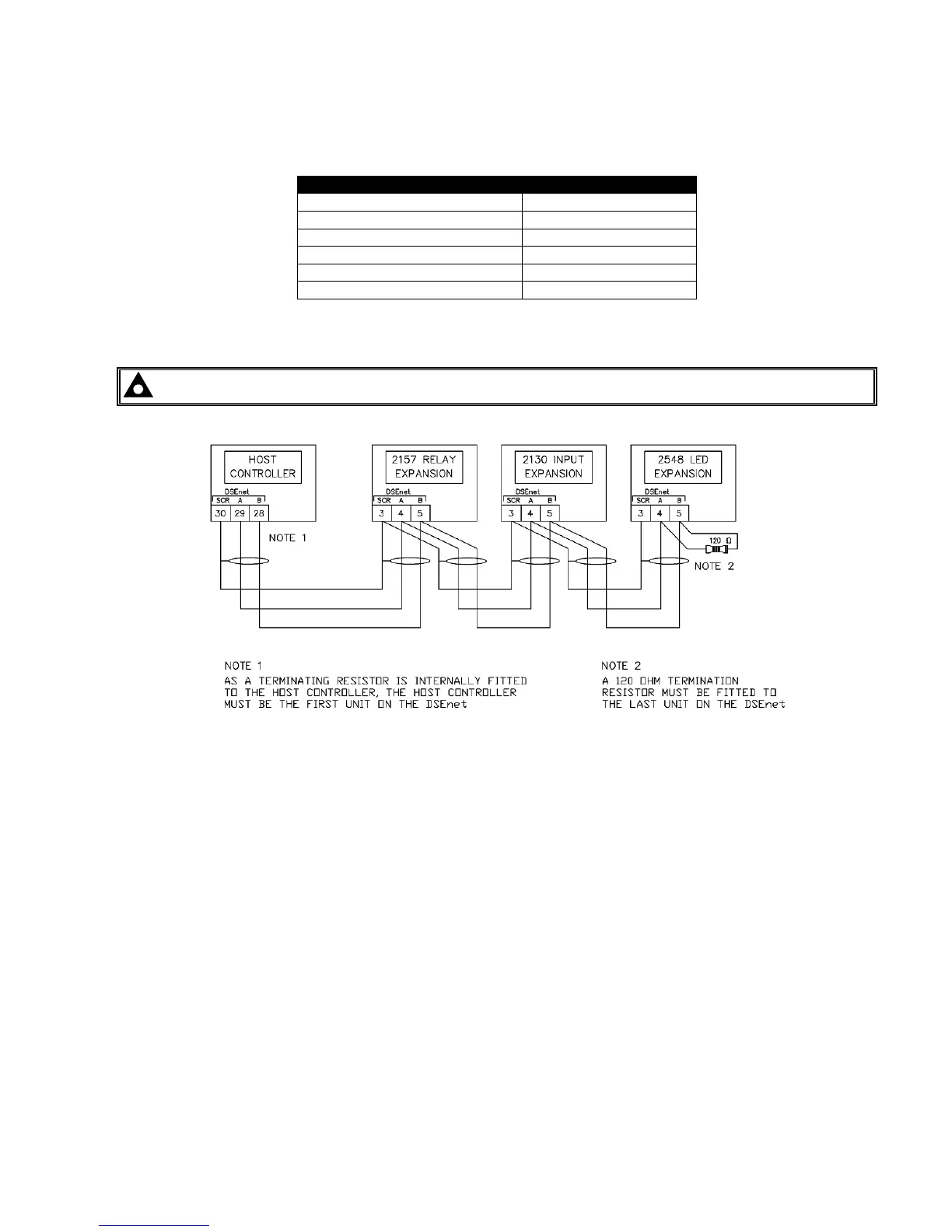
4.4 TYPICAL ARRANGEMENT OF DSENET®
Twenty (20) devices can be connected to the DSENet®, made up of the following devices :
Device Max number supported
DSE2130 Input Expansion 4
DSE2131 Input Expansion 4
DSE2133 Input Expansion 4
DSE2152 Output Expansion 4
DSE2157 Output Expansion 10
DSE2548 LED Expansion 10
For part numbers of the expansion modules and their documentation, see section entitled DSENet Expansion
Modules elsewhere in this manual.
NOTE : DSE8600 series does not support the 2510/2520 display modules.