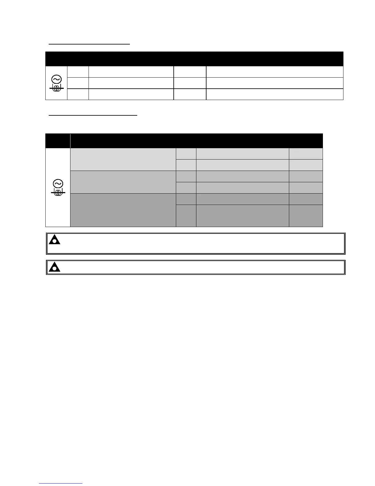
51 CT Secondary for Gen L1
2.5mm²
AWG 13
Connect to s1 secondary of L1 monitoring CT
52 CT Secondary for Gen L2
2.5mm²
AWG 13
Connect to s1 secondary of L2 monitoring CT
53 CT Secondary for Gen L3
2.5mm²
AWG 13
Connect to s1 secondary of L3 monitoring CT
Connection to terminals 54 & 55
The function of terminals 54 and 55 CHANGES depending upon what kind of earth fault protection (if any) is being used:
Topology Pin
No
Description CABLE
SIZE
No earth fault measuring
54 DO NOT CONNECT
55
Connect to s2 of the CTs connected to
L1,L2,L3,N
2.5mm²
AWG 13
Restricted earth fault measuring
54
Connect to s2 of the CTs connected to
L1,L2,L3,N
2.5mm²
AWG 13
55
Connect to s1 of the CT on the neutral
conductor
2.5mm²
AWG 13
Un-restricted earth fault measuring
(Earth fault CT is fitted in the neutral to earth
link)
54
Connect to s1 of the CT on the neutral to
earth conductor.
2.5mm²
AWG 13
55
Connect to s2 of the CT on the neutral to
earth link.
Also connect to the s2 of CTs connected to
L1, L2, L3.
2.5mm²
AWG 13
NOTE:- Take care to ensure correct polarity of the CT primary as shown overleaf. If in doubt, check
with the CT supplier.
NOTE: - Terminals 56 to 59 are not fitted to the 8610 series controller.