On burners which have air inlet silencers as standard a 0-10 scale is fitted to indicate the opening of
the air shutter (not the firing rate) and nylon support bearings ensure that the travel is as smooth as
possible.
Burner Motor
The burner (fan) motor is a continuously rated 2-pole unit with class 'F' insulation, sized according
to the application. The motor is mounted the inside of the inner shutter thus allowing 100% heat
recovery from the motor into the combustion air offering efficiency ratings greater than EFF1. This
also ensures inherently quiet operation from the burner.
Combustion Air Fan
Mounted directly onto the motor shaft and positioned within the fan case assembly, the fan supplies
combustion air via the compressor vanes and mounting casting to the combustion head.
Due to the 'T' burner requirement for extremely low vibration and noise levels the fans are
manufactured and balanced to the very highest standards (ISO 1940-2003).
All fans are colour coded according to size.
Combustion Head
The air for combustion passes from the burner fan at a pressure related to the resistance of the
boiler, down the draught tube to the combustion head. The latter is an assembly of components
which cause the gas to be discharged into the air flow in such a way that optimum mixing takes
place.
Many types of combustion head are available depending on appliance geometry, gas type, available
gas pressure, NOx level requirement etc…
Note: On any burner, an almost infinite combination of combustion head components may be used
to achieve optimum efficiency and a flame shape to suit a very wide range of heat-raising
appliances.
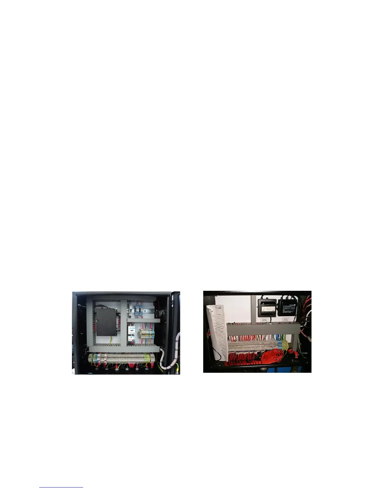
Burner Control Cabinet
Standard burners are supplied with a dust resistant damp-proof cabinet mounted on the side of the
burner. In many cases all the burner controls are fitted within the burner control cabinet (figure 1).
In more complicated installations, this cabinet would house a terminal strip (figure 2) which would
then interface to a control desk via flying leads.