41
41
41
41
3.
3.
3.
3. 6
6
6
6 .2
.2
.2
.2 The
The
The
The first
first
first
first circuit
circuit
circuit
circuit program
program
program
program
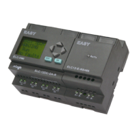
Let us now take a look at the following parallel circuit consisting of two switches.
Circuit diagram
The corresponding circuit diagram
Translated into a xLogic circuit program this means: Relay K1 is (at output Q1) is controlled by
means of an OR block.
Circuit program
S1 is connected to the I1 and S2 to the I2 input connector of the OR block.
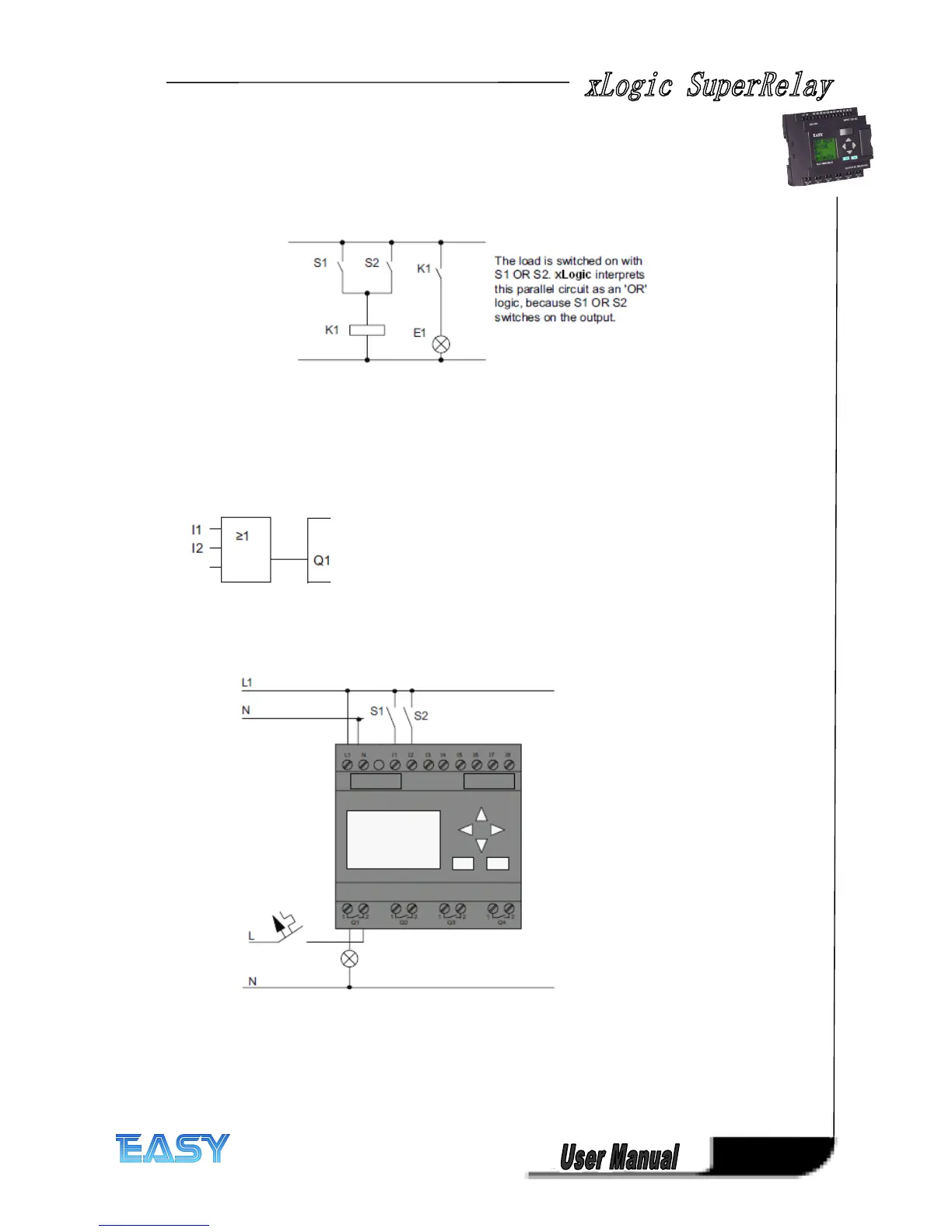
The corresponding layout of the circuit program in xLogic :
Wiring
Wiring
Wiring
Wiring
The corresponding wiring:
S1 switches input I1, while S2 switches input I2. The load is connected to the relay Q1.
3.
3.
3.
3. 6
6
6
6 .3
.3
.3
.3 Circuit
Circuit
Circuit
Circuit program
program
program
program input
input
input
input
Let us now write the circuit program, starting at the output and working towards the input.
xLogic initially shows the output: