EasyManua.ls Logo

Eaton 93PM - Figure 4-4. UPS Conduit and Wire Entry Locations

Eaton 93PM
158 pages
To Next Page IconTo Next Page
To Previous Page IconTo Previous Page
Loading...
UPS System Installation
4-8 Eaton 93PM UPS (20–100 kW, 480V – 100 kW Frame) Installation and Operation Manual P-164000227—Rev 6 www.eaton.com/powerquality
Figure 4-4. UPS Conduit and Wire Entry Locations
Bottom Entry Conduit Landing for AC
Input and Output, and DC Input
(Remove panel to drill or punch
conduit holes.)
Front
Top View
Top Entry Conduit Landings for
Customer Interface Wiring
(Remove panels to drill or punch
conduit holes.)
Bottom Entry Conduit Landings
for Customer Interface Wiring
(Remove panels to drill or punch
conduit holes.)
Front
Bottom View
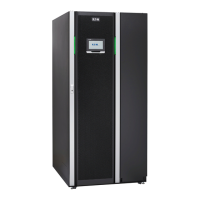
Table of Contents

Other manuals for Eaton 93PM

Related product manuals