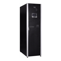
25-75 kW
User's and Installation Guide
10
The UPS is including rectifier input switch, output switch, bypass switch and MBS switch, N as default. And
for internal battery version, battery breaker will be as standard units.
If utility power is interrupted or falls outside the parameters specified in Chapter 8 Technical data, the UPS
uses a backup battery supply to maintain power to the critical load for a specified period of time or until the
utility power returns. For extended power outages, the UPS allows you to either transfer to an alternative
power system (such as a generator) or shut down your critical load in an orderly manner. The UPS bypass
consists of a continuous-duty static switch and backfeed protection isolation device K5. The backfeed
protection is located in series with the static switch. Transfers to static bypass are seamless and performed
automatically by the system as needed, for example, in case of an extended system overload.
2.2 UPS Operating Modes
UPS operating modes:
• Normaloperatingmodes:
• InDoubleConversionMode,thecriticalloadissuppliedbytheinverter,whichderivesitspower
from rectified utility AC power. In this mode, the battery charger also provides charging current
for the battery, if needed.
• InEnergySaverSystem(ESS)mode,thecriticalloadissupportedsecurelybyutilitypower
through static bypass switch with double conversion available on-demand with typically less
than a 2 ms transition time, should any abnormal condition be detected in the utility. When
operating in ESS mode, the load is protected with inherent surge suppression. Operating the
UPS in ESS mode increases system efficiency to 99 % allowing
• Instoredenergymode,theenergyisdrawnfromaDCbackuppowersourceandconvertedtoACpower
by the UPS inverter. Most commonly VRLA batteries are introduced to the system for this purpose, and
the mode of operation is called Battery Mode.
• InBypassMode,thecriticalloadissupporteddirectlybyutilitypowerthroughtheUPSstaticswitch.
2.2.1
Normal Operating Modes
During normal UPS operation, power for the system is derived from a utility input source. “Unit Online” is
displayed on the front panel, indicating that the incoming power is within voltage and frequency acceptance
windows.
2.2.1.1
Double Conversion Mode
Figure 2-4: Path of current through the UPS in Double Conversion Mode shows the path of electrical power
through the UPS system when the UPS is operating in Double Conversion Mode.

 Loading...