25-75 kW
User's and Installation Guide
50
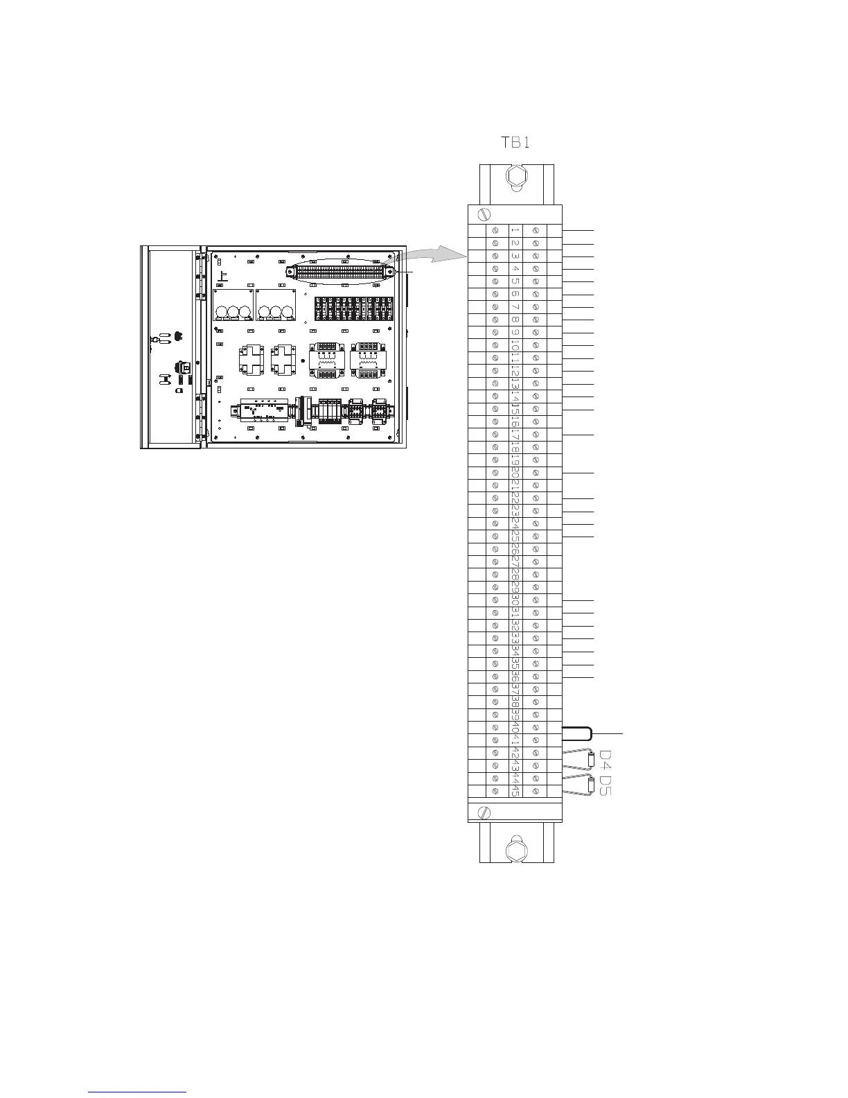
4.5.4 Installing Eaton Sync Control
Refer to the operating instructions provided with the
Eaton
Sync Control.
UPS System−A – Bypass Voltage Phase A
UPS System−A – Bypass Voltage Phase B Return
UPS System−A – Bypass Voltage Phase B
UPS System−A – Bypass Voltage Neutral
UPS System−B – Bypass Voltage Phase A
UPS System−B – Bypass Voltage Phase B
UPS System−B – Bypass Voltage Neutral
UPS System−B – Bypass Voltage Phase B Return
UPS System−A – Output Voltage Phase A
UPS System−A – Output Voltage Phase B
UPS System−A – Output Voltage Neutral
UPS System−B – Output Voltage Phase A
UPS System−B – Output Voltage Phase B
UPS System−B – Output Voltage Neutral
On Bypass Common
UPS System−A – On Bypass NO
UPS System−B – On Bypass NO
UPS System−A – Building Alarm 1 (see Note)
UPS System−A – Building Alarm 1 Return
UPS System−B – Building Alarm 1 (see Note)
UPS System−B – Building Alarm 1 Return
Jumper
Common Return
UPS System−A – Active Master Source
UPS System−B – Active Master Source
UPS System−A – Synchronized to Load B
UPS System−B – Synchronized to Load A
Load Sync Enabled
Common Return
Figure 4-12: Sync Control TB1 Terminal Location

 Loading...


