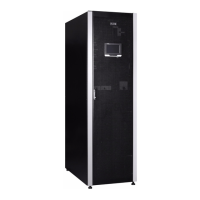
25-75 kW
User's and Installation Guide
68
Note:
• The “Permitted Maximum Power” does not mean that the UPS will be overloaded if this power value is
exceeded. For example, when selecting the 2+2 configuration, the rated UPS apparent power is 100kVA
and active power is 100kW, therefore, if load exceeds the permitted maximum power 50kW (permitted
maximumpower),theUPSwillnotbeoverloadedandonlytheN+X(X=2)structurewillbechanged.
• The “permitted maximum power”indicates the three-phase power, so the permitted maximum power of
single-phase needs to be divided by three.
Adding the UPS Module
Online
1. Choose anyone plastic cover; UPM should be installed one by one.
WARNING
Theplasticpanelmustbeinstalled,ifthecardslotisnotinserted,otherwiseitwillcausehotairreturnattherear.
2. Remove 2pcs screw shown above and take plastic cover away. We can see the view from the front and 3
screws pre-installed, see Figure. 6-8
②
.
WARNING
Donotremovethesescrews
②
.
3. Set the position lock located on the front panel of the module to “ ”.
4. After UPM is installed, switch UPM lock in lock state, see Figure. 6-8
③
.
5. Right side is unlock state and the other side is lock state, see Figure. 6-8
④
.
6. Fix 2pcs screws to finish the installation and set the position lock located on the front panel of the module
to “ ” (see Figure. 6-8).
Reducing/ReplacingtheUPSModuleOnline
Removing UPM has reversed steps as adding UPM, please remove UPM from step 6 to step 1.
To replace UPM, please implement removing UPM steps and then do adding UPM steps.
WARNING
• BeforetheLEDisoff,itisforbiddentopullouttheUPMmodule.
• Ensurethelockhastounlockthestate,whenpullouttheUPM.

 Loading...