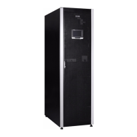
25-75 kW
User's and Installation Guide
viii
List of Figures
Figure 2-1. Eaton 93PR UPS ....................................................................... 7
Figure 2-2. 93PR 25-75 kW UPS Wiring Diagram (Without Internal Battery Version) ............................ 8
Figure 2-3. 93PR 25-75 kW UPS Wiring Diagram (With Internal Battery Version) ............................... 9
Figure 2-4. Path of Current Through the UPS in Double Conversion Mode .................................... 11
Figure 2-5. Path of Current through the UPS in Energy Saver System ....................................... 12
Figure 2-6. Path of Current through the UPS in Battery Mode ............................................. 13
Figure 2-7. Path of Current through the UPS in Bypass Mode ............................................. 14
Figure 2-8. Two-switch MBS Electrical Connection Drawing .............................................. 17
Figure 2-9. Three-switch MBS Electrical Connection Erawing ............................................. 18
Figure 3-1. UPS Cabinet Clearances. See Table 3-3. ..................................................... 24
Figure 3-2. 93PR 25-75 kW UPS Dimensions ......................................................... 25
Figure 3-3. UPM Dimensions ...................................................................... 26
Figure 3-4. Remove all Fixed Shipping Brackets and Screw Fixed on the Pallet. ................................ 33
Figure 3-5. Attaching the Ramp to the Pallet .......................................................... 33
Figure 3-6. Rolling the Cabinet Down the Ramp ........................................................ 33
Figure 3-7. Instruction for Removing the Module Packaging .............................................. 34
Figure 3-8. Instruction for Femoving the Battery Module Packaging ......................................... 35
Figure 4-1. 93PR 25-75 kW Gland Plate and Connector Locations (With Internal Battery Version) .................. 37
Figure 4-2. 93PR 25-75 kW Gland Plate and Connector Locations (Without Internal Battery Version) ............... 38
Figure 4-3. Take Out the Battery Modules from the Package .............................................. 39
Figure 4-4. Open the Battery Terminal Cover .......................................................... 39
Figure 4-5. Install the Battery Module ............................................................... 40
Figure 4-6. Connections of the EPO Switch ........................................................... 42
Figure 4-7. Principle of Paralleled UPS Systems ........................................................ 46
Figure 4-8. Communication Interfaces ............................................................... 47
Figure 4-9. Pimplified CAN and Pull-Chain Wiring for Parallel UPP System .................................... 48
Figure 4-10. CAN and Pull-Chain Wiring for Parallel UPP with MOBs ......................................... 48
Figure 4-11. CAN and Pull-Chain Wiring for Parallel UPP without MOBs ...................................... 49
Figure 4-12. Sync Control TB1 Terminal Location ........................................................ 50
Figure 5-1. Communication Interfaces ............................................................... 51
Figure 5-2. Network Card-MS ..................................................................... 52
Figure 5-3. PX Gateway Card ...................................................................... 52
Figure 5-4. Relay Card-MS ........................................................................ 53
Figure 5-5. Network and MODBUS Card - MS ......................................................... 53
Figure 5-6. Industrial Relay Card-MS ................................................................ 54
Figure 6-1. UPS Switch Position .................................................................... 56
Figure 6-2. Parts of the Display ..................................................................... 57
Figure 6-3. Green Symbol ........................................................................ 58
Figure 6-4. Yellow Symbol —Battery Mode ........................................................... 58
Figure 6-5. Green Symbol ........................................................................ 58
Figure 6-6. Yellow Symbol-Battery Mode ............................................................. 58
Figure 6-7. UPS Status Lights ..................................................................... 59
Figure 6-8. UPM Module Location .................................................................. 69
Figure 6-9. The normal Positions of the MBS Switches and Rectifier Disconnect Switch ......................... 72
Figure 6-10. Maintenance Bypass Mode .............................................................. 72
Figure 6-11. Maintenance Bypass Mode .............................................................. 73
Figure 6-12. Double Conversion Mode ................................................................ 73
Figure 6-13. STS Module .......................................................................... 74
Figure 7-1. WEEE Symbol ........................................................................ 77
Figure 7-2. Recycling Batteries Symbol .............................................................. 78

 Loading...