4 Creating a planned SmartWire-DTSmartWire-DT configuration in SWD-Assist
4.8 Storing the planned SmartWire-DT configuration
40 SmartWire-DT Gateway EU5C-SWD-EIP-MODTCP 08/17 MN120003Z EN www.eaton.com
These include, for example, "Contactor model" and "Profile" for the PKE-SWD-
32 device model; see example → Figure 23.
Likewise, various data profiles that define the scope of I/O data that is trans-
mitted cyclically can also be defined.
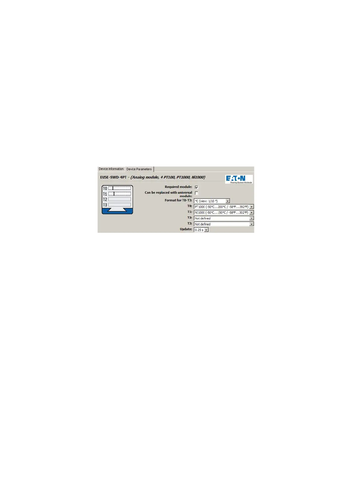
Device-specific parameters for the EU5C-SWD-4PT analog module include,
for example, selecting the analog sensor that must be connected, which can
be selected using the "T0" and "T1" drop-down menus, and scanning time
specifications, which can be selected using the "Refresh" drop-down menu.
These settings are found in the "Device parameters" tab for the module.
For information regarding the parameter configuration options available for
individual SmartWire-DT modules, please consult the "SmartWire-DT Mod-
ules IP20", MN05006001Z.
Figure 24: Device parameters of EU5E-SWD-4PT SmartWire-DT temperature module in
SWD-Assist
4.8 Storing the planned SmartWire-DT configuration
▶ In order to establish a connection to the device, first switch to the Com-
munication view by clicking on the "View" > "Communication view" but-
tons.
▶ Click on the "Connection setup" button and then on the "Online" button.
▶ Click on the "Configurations in device" button
▶ Under "Planned configuration," click on "PC=>Device"
The planned SmartWire-DT configuration is now stored in the gateway. The
Config LED will show a solid green light.
 Loading...