8 What you need to know about SmartWire-DT
8.4 Cyclical input and output data of the SWD modules
SmartWire-DT Gateway EU5C-SWD-EIP-MODTCP 08/17 MN120003Z EN www.eaton.com 89
The diagnostic bits of the individual SWD modules can be looked up in the
"SmartWire-DT Modules IP20", MN05006001Z.
Example for output data:
The M22-SWD-K11-LED-R function element has a red LED for illuminated
pushbuttons and the two switch states 0 and 1. With cyclical output data of
one byte, it contains information on switch position and diagnostic informa-
tion.
Byte 0:
Extended diagnostic services
If a SWD module is signaling "Diagnose," i.e., if bit 4 of input byte 0 is set to
1, the corresponding details can be obtained by evaluating the extended diag-
nostic services.
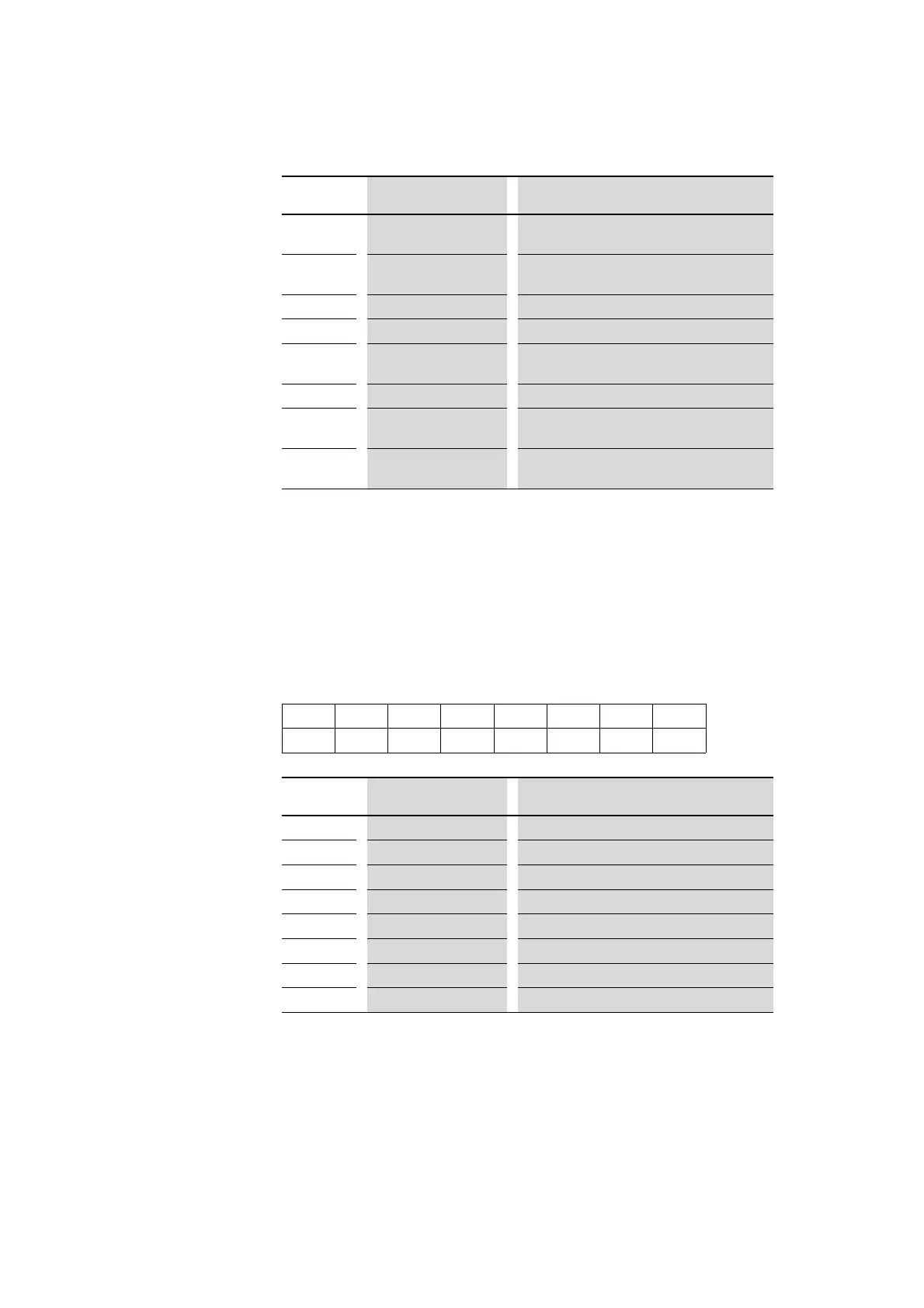
BIT designation Meaning
0 NC1 = Normally Closed 0: contact actuated
1: contact not actuated
1
NO1 = Normally Open 0: contact not actuated
1: contact actuated
2
Not used -
3 Not used -
4 DIAG 0: no diagnostic alarm
1: Diagnostic alarm present
5
Not used -
6
PRSNT 0: module not present
1: module present
7
SUBST 0: planned module is present
1: M22-SWD-NOP(C) universal module present
76543210
–––––––Q0
BIT
designation Meaning
0 Q0 Control section LED
1 Not used –
2
Not used –
3
Not used –
4 Not used –
5 Not used –
6 Not used –
7
Not used –




 To Next Page