BATTERY
BREAKER
UPS SYSTEM ONELINE DRAWING
032406D
164201554---4
DESCRIPTION:
DATE:
DRAWING NO: SHEET:
REVISION:
UPS CABINET
INVERTER
RECTIFIER
STATIC
SWITCH
REMOTE EPO
BUILDING ALARMS
AC OUTPUT
TO
CRITICAL LOAD
AC INPUT TO
UPS RECTIFIER
3 W IRE A --- B --- C
AC INPUT
TO BYPASS
3 o r 4 W I R E A --- B --- C
ROTATION
ROTATION
(See Drawing 164201554---8)
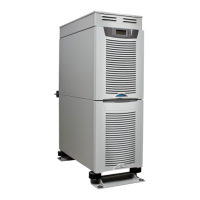
POWERWARE 9390 100–160 KVA UPS SYSTEM
480V INPUT AND 480V OUTPUT
SINGLE-FEED OR DUAL-FEED
INPUT
CONTACTOR
(K1)
BATTERY
CONVERTER
BATTERY
CABINET
X-SLO T
INTERFACE
(Optional)
(DUAL FEED)
(DUAL FEED)
FUSE
BACKFEED
CONTACTOR
(K5)
OUTPUT
CONTACTOR
(K3)
E4. E5
E9, E10,
E11, E12
FUSE
ALARM RELAY
FUSE
INTERFACE
BOARD
BATTERY AUX
BATTERY UVR
A
B
C
D
E1, E2, E3 E6, E7, E8, E12
SEENOTE2
AC INPUT TO
UPS RECTIFIER AND BYPASS
(SINGLE-FEED)
3 o r 4 W I R E A --- B --- C
ROTATION
NOTE: 1. A minimum of two separate feeds with
upstream feeder breakers, or one feed
with two upstream feeder breakers, must
be provided: one for the UPS and one
for the IAC bypass input. DO NOT use
one feed or a single feeder breaker to
supply both the UPS and the IAC
.
2. Remove jumper for dual-feed.
3. If the load requires a neutral, a bypass
neutral feeder must be supplied.
1of6
Installation Information
A-6
EATON Powerware
®
9390 UPS (100–160 kVA) Installation and Operation Manual S 164201554 Rev E powerware.com

 Loading...


