General Description
Copyright © 2007-2011 Eaton Corporation. All Rights Reserved.
IPN 997-00012-50H November 2011
The I/O functions are:
Current - 3, Bus voltage - 1, Temperature - 2, Battery Mid-point - 4
Digital inputs: 4 pre-defined system functions, 6 user-defined
Relay outputs: 6 (one also used as Monitor OK alarm)
LVD contactor outputs: 2
For input and output specifications see details on page 105. For connector pin-outs see details on
page 114.
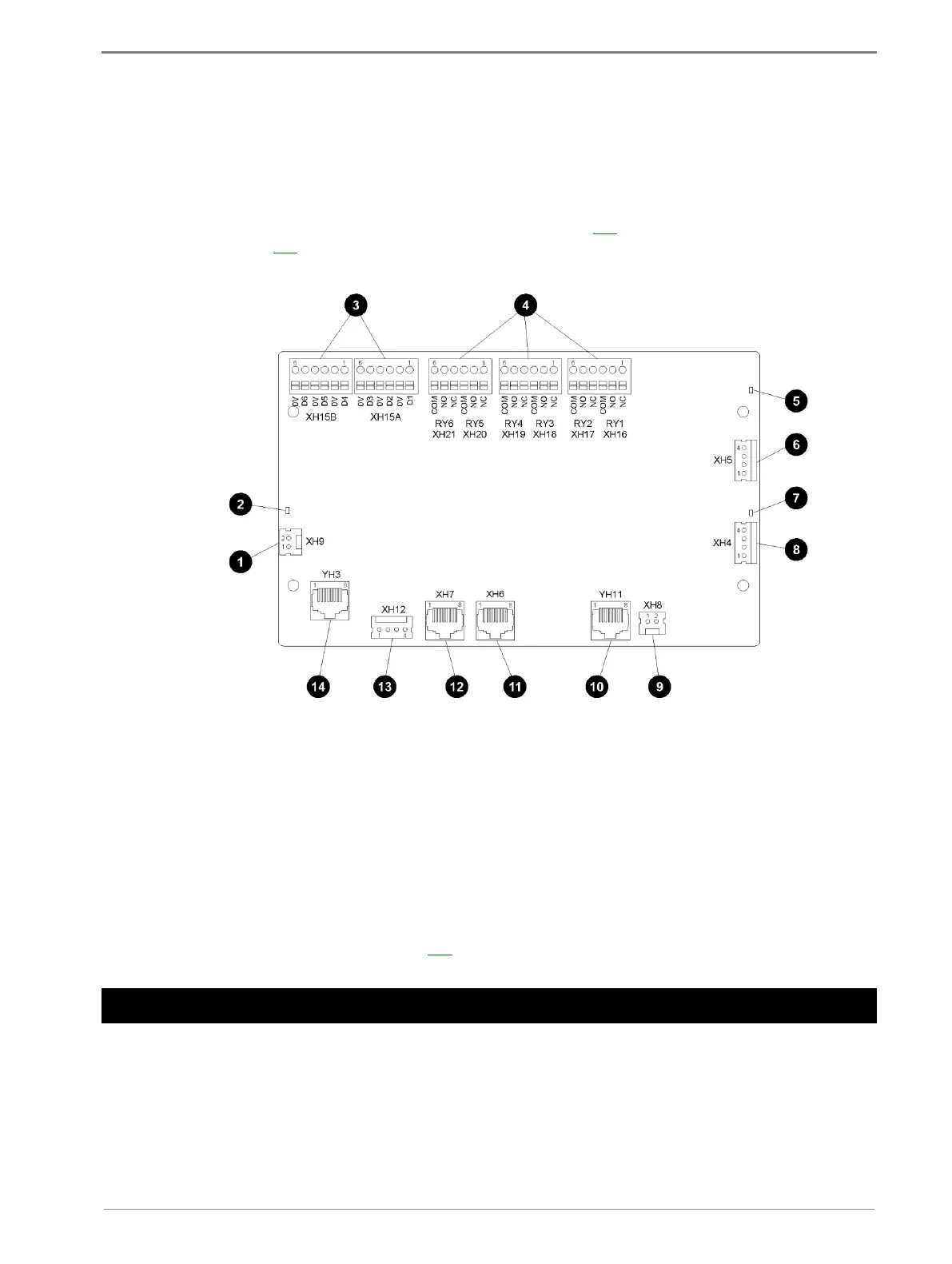
Bus voltage sense input - XH9
Power/Comms OK LED (green)
Digital inputs D1-D6 (6 user defined) - XH15A,
XH15B
Digital (relay) outputs RY1-RY6 (6) - XH16-XH21
LVD contactor 2 status LED (green)
LVD contactor 2 connector - XH5
LVD contactor 1 status LED (green)
LVD contactor 1 connector - XH4
LVD power input connector - XH8
Power and RXP comms input - YH11
Current sense inputs (3) - XH6
Temperature sense inputs (2) - XH7
Battery Mid-point Monitoring sense inputs - XH12
DC power system digital inputs (4 pre-defined:
Load Fuse Fail, Battery Fuse Fail, AC Distribution
Fan Fail, AC Distribution MOV Fail) - YH3
See Troubleshooting on page 100 for details of I/O board LED signals.
Connections
The following diagram shows the connections between the SC200, the I/O board, the other dc
power system components and external devices.

 Loading...


