1.
Output for the SPIR410
The output is performed via the "compressor enable" output and the analogue output AO1 for output of
the compressor speed.
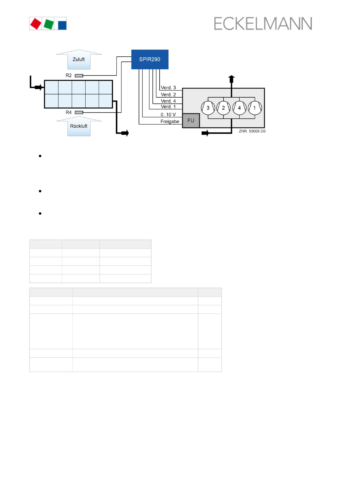
Output for the SPIR290
With speed control
The output is performed via the "compressor enable" output, the outputs for switching on the up to four
compressors and the analogue output AO1 for output of the compressor speed.
With step-by-step switching
The output is performed via the "compressor enable" output and the outputs for switching on the up to
four compressors. The calculated speed is shifted to the compressor stages as described.
Switch off below Switch on starting from
Compressor 1 5 % 20 %
Compressor 2 40 % 55 %
Compressor 3 60 % 75 %
Compressor 4 80% 95 %
Description Terminals
R2 Supply air sensor R2 11/12
R4 Return air sensor R4 21/22
Compressor 1..4 Relay output for control of the compressors
Compressor 1
Compressor 2
Compressor 3
Compressor 4
25/26/28
53/54
63/64
43/44
Compressor enable Relay output for the enable of the compressors on the FC 35/36/38
Compressor speed
(FC frequency)
Analogue output AO1 (0..10 V corresponds to 0..100%) 29/30
Calculation of the compressor speed
The compressor speed is calculated between 0 .. 100% using a PID controller. The calculation and output of
the compressor speed are performed after enable of the cooling (see chapter Temperature regulation
) using the temperature sensor R2 and the R2 setpoint. If R4 according to supply air and return air, page 22
undercuts the R4 setpoint, the setpoint of R2 is increased linearly.
Case: Return air < return air - 2 K
Actual value Setpoint