Controller type Transistor output 1:
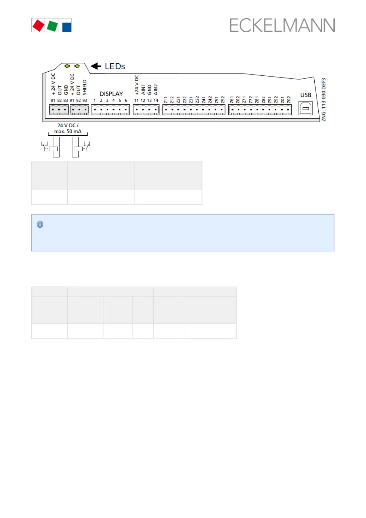
81: 24 V DC / max. 50 mA
82: OUT
83: GND
Transistor output 2:
91: 24 V DC / max. 50 mA
92: OUT
93: SHIELD
SPIR410 /
SPIR290
Lighting control
(terminals 81/82)
Frame heater
(terminals 91/92)
If any transistor output is activated by the controller, the associated green LED lights; for details see
chapter . For further details about the function of the outputs, see chapter Status LEDs, page 47
Function of the relay and transistor outputs., page 70
7.7.1 Function of the relay and transistor outputs
The table shows the function of the outputs of the individual controller types.
Relay outputs 230 V AC Transistor outputs 24 V DC/50 mA
Controller type Condenser or
evaporator fan
(ventilator)
Compressor
control /
compressor
enable
Alarm Lighting Frame heater
SPIR410 /
SPIR290
positive positive inverted positive inverted