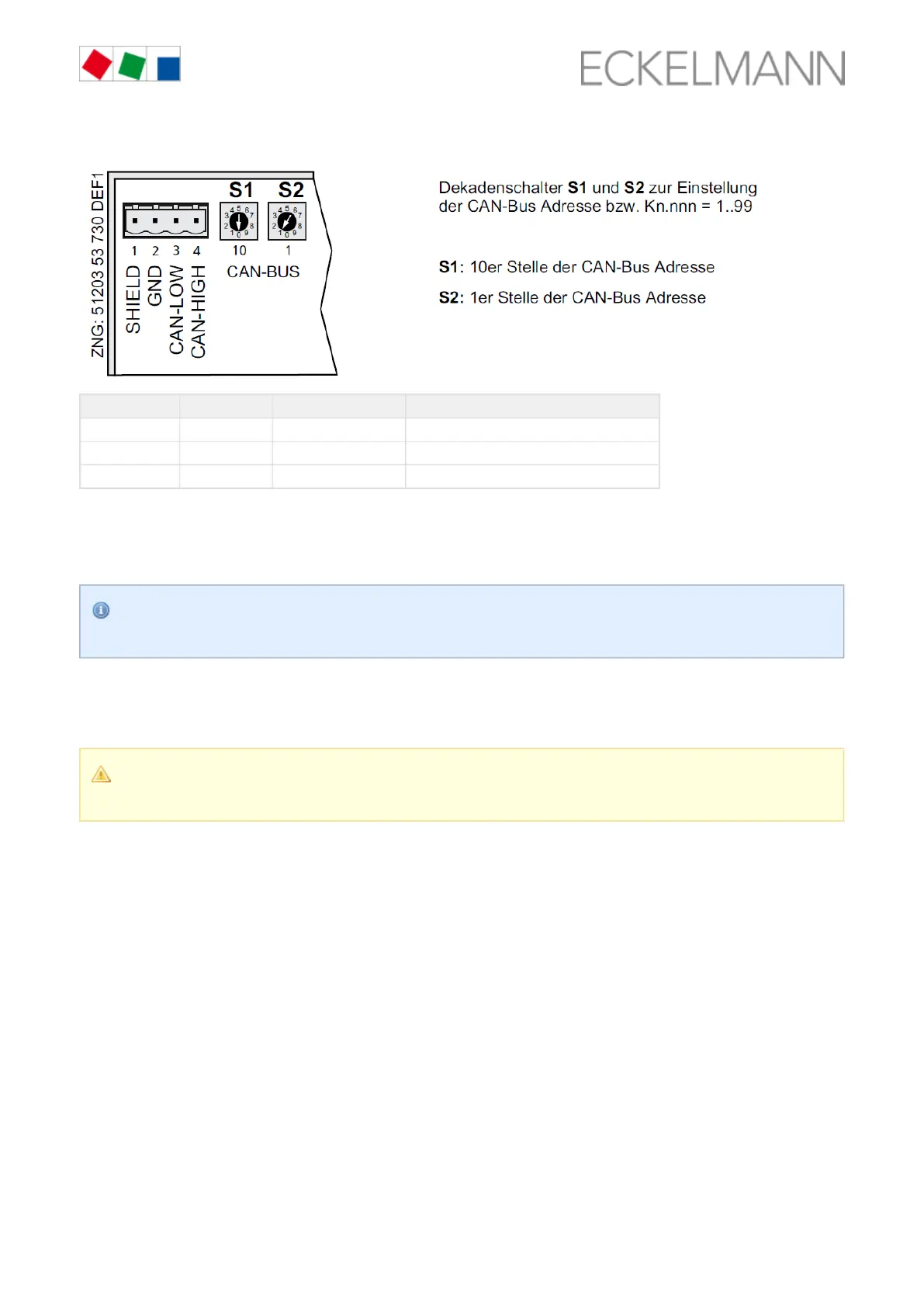
S1 (10 position) S2 (1 position) Set CAN bus address Function
0 0 00 CAN bus interface inactive (disabled):
0 1..9 01..09 Case controller: CAN bus address assigned
1..9 0..9 10..99
Example:
S1 = 3 = 3 x 10 = 30 and = 4 = 4 x 1 = 4S2
CAN bus address = S1 + S2 = 30 + 4 = 34
The case controller does not accept the settings on the decade switches and until after the S1 S2
controller has been briefly disconnected from the power supply!
6.4 Setting of the controller type and master/slave mode
Caution: data loss! All parameters are reset to their factory settings if the controller type is changed
or due to a first start (see chapter )!First start / reset controller to factory settings, page 19
Setting of the controller type
The required controller type can be set via the by adjusting the coding switches 1..9 with a thin DIP switch S3
screwdriver (D = 2 mm) through a hole in the case cover: