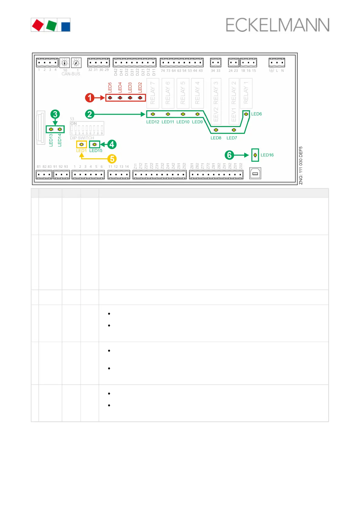
Function Colour LED Description
1 Digital
inputs
red LED2
LED3
LED4
LED5
ON: Digital input 1 is activated (terminals D11/D12)
ON: Digital input 2 is activated (terminals D21/D22)
ON: Digital input 3 is activated (terminals D31/D32)
ON: Digital input 4 is activated (terminals D41/D42)
ATTENTION: External voltage can be present at these terminals!
2 Relay
outputs
green LED6
LED7
LED8
LED9
LED10
LED11
LED12
ON: Relay 1 is switched (terminals 15/16/18)
ON: Semi−conductor relay 2 (EEV1) is switched (terminals 23/24)
ON: Semi−conductor relay 3 (EEV2) is switched (terminals 33/34)
ON: Relay 4 is switched (terminals 43/44)
ON: Relay 5 is switched (terminals 53/54)
ON: Relay 6 is switched (terminals 63/64)
ON: Relay 7 is switched (terminals 73/74)
ATTENTION: External voltage can be present at these terminals!
3 Transistor
outputs
green LED13
LED14
ON: Transistor output 1 is switched (terminals 81..83)
ON: Transistor output 2 is switched (terminals 91..93)
4 LIFE green LED15
FLASHING
Active lamp, controller is supplied with power, processor is running
OFF
Power supply interrupted or device defective
5 CAN bus orange LED1
FLASHING
LED always flashes when data are being exchanged via the CAN bus with the system centre / store
computer.
OFF
CAN bus connection interrupted or CAN bus defective
6 USB green LED16
ON
Connected to PC or data exchange via USB port
OFF
USB connection interrupted or USB connection defective
6.6 Basic configuration of the controller
CI 3x00 store computer / AL 300 operator terminal, page 82
The lock-down must previously be deactivated on the higher level controller (system centre / store computer or