50Installation and Service Guide Color Controller E-46A
Replacing parts
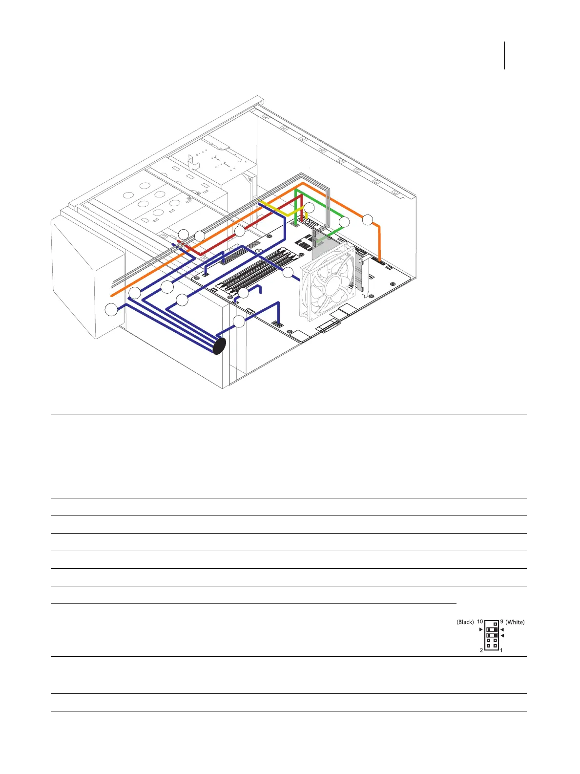
Figure 27: Power and data cable connections
Cable key From To
1 Power supply cable Power supply a. 24-pin power connector on motherboard (J18)
b. 8-pin power connector (PWRCONN1)
c. DVD drive power connector
d. Hard disk drive power connector
e. Fiery QuickTouch power connector
2 Fiery QuickTouch USB cable Fiery QuickTouch USB3.0 header connector on motherboard (J26)
3 SATA Data cable DVD drive SATA 0 connector on motherboard (J50)
4 SATA Data cable Hard disk drive SATA 1 connector on motherboard (J41)
5 Rear fan cable Rear fan FRONT FAN connector on motherboard (J20)
6 CPU fan cable CPU fan CPU FAN connector on motherboard (J16)
7 Power switch cables (red, white) Fiery QuickTouch J102 connector on printer interface board (pin 5, 6) Align triangle on
cable connector
as shown.
8 LED cables (white, black) Fiery QuickTouch J102 connector on printer interface board (pin 7, 8)
Note: When polarity (+/-) is right, the LED of the
power button turns on.
9 Cable with keyed connectors J103 connector on
printer interface
board
FP header connector on motherboard (J15)
Note: See the cable connection label attached inside the chassis.
1b
1c
7
1a
1d
3
2
4
5
6
1e
8
9
LED +LED -
SW