61Installation and Service Guide Color Controller E-46A
Replacing parts
This section also includes information about the following:
• Replacing or adding DIMMs
• Replacing the CPU
• Replacing the battery
• Jumper configurations
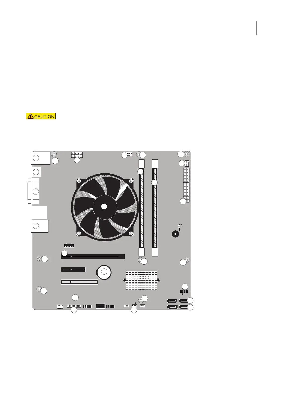
Figure 33: Motherboard
Follow standard ESD and other safety precautions when handling components (see page 12).
During service to the motherboard, avoid using excessive force and always place the motherboard
on a grounded, non-metallic, static-free surface. Never allow any metal to touch the solder contacts
on the underside of the motherboard, especially beneath the battery socket. Improper handling can
short-circuit and permanently damage the motherboard.
1 Type A USB 2.0 ports and
network port
6 CPU cooling assembly 11 CPU fan power (CPU FAN,
J16)
16 SATA 0, DVD drive data
cable connector (J50)
2 Monitor port (DisplayPort) 7 Printer interface board
(PCIE_X16_SLOT)
12 Rear fan (FRONT FAN, J20) 17 SATA 1, Hard disk drive
data cable connector (J41)
3 Monitor port (DVI) 8 Battery (CR1) 13 24-pin power connector
(J18)
18 Clear CMOS Jumper (J101)
1
4
8
2
7
3
5
10
6
MH
MH
MH
MH
MH
MH
MH
MH
11
13
14
15
16
17
18
12
MH
9