EasyManua.ls Logo

Eilersen 5024G - User Manual

Default Icon
39 pages
Print Icon
To Next Page IconTo Next Page
Loading...
Software: StdLim.140630.5v7
Doc. no.: StdLim-140630-5v7-UG-eng
Date: 2020-09-08
Rev.: 5v7
Contact:
Eilersen Electric A/S
Kokkedal Industripark 4
DK-2980 Kokkedal
Denmark
www.eilersen.com
info@eilersen.com
Tel: +45 49 180 100
Fax: +45 49 180 200
5024G User’s guide StdLim
5024G LCD weighing terminal
Basic scale with automatic dosing

Table of Contents

Other manuals for Eilersen 5024G

Questions and Answers

  • T
    Tristan PriceSep 12, 2025
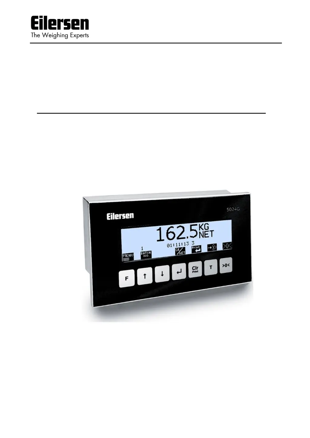
    What to do if Eilersen 5024G display -XXXX-?
    • D
      Douglas PalmerSep 12, 2025
      If '-XXXX-' is displayed on your Eilersen Accessories, it signifies a load cell error. Ensure the load cell configuration is correct and that the system has been power-cycled. Check all load cell connections and refer to the load cell documentation for more information, including the error code display and STATUS screen details.
  • Z
    Zachary LinAug 23, 2025
    What to do if there is no connection between PLC and external module with Eilersen Control Unit?
    • G
      gmartinezAug 23, 2025
      If you are experiencing a lack of connection between the PLC and the external module when using the Eilersen Control Unit, consider the following checks: * Ensure the field bus cabling between the 5024G and PLC is correctly connected. * Verify the field bus termination is properly configured. * Confirm that the external module is receiving power. * Check that the PLC is configured correctly, potentially using the provided configuration file. * If possible, ensure the field bus communication address is correctly set, using DIP switches or a configuration tool. * Examine the status lamps on the external module to see if they indicate a successful connection to the PLC.
  • H
    Hannah GarrettAug 27, 2025
    Why is Eilersen Control Unit's implemented protocol not behaving as expected?
    • J
      joshua07Aug 27, 2025
      If the implemented protocol on your Eilersen Control Unit is not behaving as expected, use the EXTERNAL MODULE DATA screen to debug. Verify that the data (IN) received by the 5024G from the PLC results in the expected transmit data (OUT) to the PLC.
  • D
    David HigginsAug 28, 2025
    What to do if PLC is unable to receive/transmit data from/to Eilersen 5024G Touch terminals?
    • C
      Crystal JohnsonAug 28, 2025
      If the PLC is unable to receive or transmit data from/to the 5024G terminal, verify the connection between the PLC and the 5024G terminal. Also, check the configuration of both the 5024G terminal and the Ethernet-IP master (PLC). Finally, check the 'EtherNetIP' status in the ETHERNET STATUS screen.
  • L
    Logan Johnson Jr.Aug 29, 2025
    How to troubleshoot no connection between PLC and Eilersen 5024G Touch terminals?
    • J
      Jerome HarrisonAug 29, 2025
      To troubleshoot a lack of connection between the PLC and the 5024G terminal: * Ensure the Ethernet cable is correctly connected to both the PLC and 5024G. * Check the Ethernet cable for any damage. * Examine the status of the green and yellow lights on the Ethernet connectors.
  • C
    Christopher RamirezAug 31, 2025
    What to check if there is a wrong configuration of PLC for Eilersen Touch terminals?
    • D
      Diane DouglasAug 31, 2025
      Verify that the PLC is correctly configured, possibly using the supplied EDS file. Ensure that 14 input bytes and 14 output bytes are used in this application. Also, confirm that the PLC is configured with the correct IP address and Subnet mask.
  • S
    Summer Harrington DVMSep 22, 2025
    What to do if no keyboard icons are shown on Eilersen Accessories?
    • J
      James McmillanSep 22, 2025
      If no keyboard icons are shown on your Eilersen Accessories, the keyboard is locked. Press any key, then press the indicated key sequence until the keyboard unlocks.
  • S
    Sherri HallNov 23, 2025
    What to do if there is no connection between 5024G and external module with Eilersen Control Unit?
    • T
      Taylor RichardsonNov 24, 2025
      If there's no connection between the 5024G and the external module, check these items: 1. Make sure the RS485 connection between the 5024G and the external module is correctly wired. 2. Confirm the external module is properly powered. 3. Verify the AUX (RS485) communication address is correctly set on the external module using its DIP switches. 4. Check if the status lamps (typical TXBB and D1) on the external module indicate communication with the 5024G (they should toggle). 5. Ensure the parameters in the EXTERNAL MODULE screen are correctly configured: * The ”Device Type” parameter matches the external module type. * The ”Address” parameter corresponds to the DIP switch setting on the external module. * The ”Bytes Out” parameter matches the specification in the c...
  • C
    Cody StevensSep 9, 2025
    What to do if Eilersen 5024G display UL or OL?
    • T
      Tara DavisSep 9, 2025
      If your Eilersen Accessories display 'UL' or 'OL', it indicates the weight is outside the weighing range. First, check the installation for any mechanical errors, such as surrounding objects touching the weighing arrangement. Verify that the load isn't too heavy for the scale's capacity and that the load cell and weighing range configuration are correct. Empty the system, then zero it, initially during operation. If that's not enough, zero it during power-up. As a last resort, perform a coarse taring operation when the system is empty.
  • R
    Richard RosarioSep 6, 2025
    What to do if there is no connection between Eilersen Monitor 5024G main terminal and remote display?
    • R
      Rachel MooreSep 6, 2025
      If there's no connection between the 5024G main terminal and the remote display, and the remote display shows “-- -----“, verify the RS485 connection between the devices is correctly established. Ensure the 5024G remote display is properly powered. Also, check the parameters in the REMOTE DISPLAY screen on the 5024G main terminal, making sure that the "Device Type" matches the 5024G remote display (5024), the "Address" parameter corresponds to the 5024G base address (c0), the "Endian" parameter matches the 5024G remote display (LSB), the "Bytes Out" parameter matches the specification (typically 14), and the "Bytes In" parameter also matches the specification (typically 14).

Summary

Installation

Perform basic operations

Details on the steps needed to install the system are explained below.

Weight reading

Status indications

Keys;actions

Perform automatic dosing

Change setpoints for automatic dosing

Setting Coarse and Fine limits

Specifies COARSE and FINE setpoints to control dosing speed and desired amount.

Start;Stop of dosing

How to start or stop dosing using the keyboard or digital START input.

Change dosing parameters

Change registration period

Setting the time from dosing finish to automatic registration in milliseconds.

Change afterflow status

Enabling or disabling afterflow correction (OFF, ON, AUTO).

Change afterflow correction

Adjusting the actual afterflow correction parameter for dosing completion.

Reading totals

Reset of totals

Operate the menu system

Set date and time

How to set the internal clock's date and time via the SETUP menu.

Unlock the keyboard

Unlock for parameter update

Enter values

Entry using selection list

How to select parameter values from a pull-down menu.

Entry of numbers

How to enter numerical values using a data entry screen.

Check the software version

Activate Intelligent Setup

Set up the load cell configuration

Load cell communication protocol type

Number of load cells

Number of supports

Detect the load cell configuration

Configure the weighing ranges

Perform coarse taring

Configure display, filtering and stability requirement

Interval

Setting the display update interval in milliseconds for steady readings.

Filters

Applying filters to sampling and display weight readings.

Steady;stability detection

Defining when weight is considered stable within entered limits.

Perform load check

Perform corner calibration

Corner calibration procedure

Corner calibration factor

Changing or specifying corner calibration factors manually or via calibration.

Reset corner calibration factors

Procedure to reset corner calibration factors to default values.

Corner calibration procedure details

Perform system calibration

Calibration factor

Changing or specifying the system calibration factor.

Calibration load

Specifying the mass of the load used for calibration.

Perform calibration

Perform linearization

Load points

Up;Down corrections

Hysteresis limit

Reset linearization

Configure Ethernet settings

Address settings

How to set IP, subnet, and MAC addresses via EEConnect or the terminal.

Configure Ethernet TCP communication

Enable TCP protocol

Enabling the TCP protocol in the ETHERNET PROTOCOLS screen.

Select TCP port

Setting the used TCP port number for communication.

Select data output

Check Ethernet communication status

Check load cell serial no., exponent and capacity

Check individual load cell signals

Check load cell diagnostics

Trouble shooting

Error situations

Lists common error messages and their possible explanations and solutions.

Error code display (in NORMAL screen)

Error solving (in STATUS screen)

Appendix A - Installation checklist

Appendix B - Electrical connections

Power Connection

How to connect the 24VDC power supply to the terminal.

Load cell connection

Digital I;O connector

RS485 communication

Analog output connector

Ethernet connector

Jumper settings

Light Emitting Diodes (LEDs)

Appendix C - Screen overview

Appendix D - Filters

Sampling filter

How sampling frequency and filter frequency depend on load cell communication.

Load cell protocol type

Display and steady filters

Appendix E - Setting of MAC Address

Appendix F - Software download

Appendix G - Advanced features

Revision History

Contact

Eilersen 5024G Specifications

General IconGeneral
CategoryAccessories
TypeLoad Cell
Output Sensitivity2 mV/V
MaterialStainless Steel
Protection ClassIP68