06/2011 - Art. Nr. 13 018 118C
46
Regulating the burner for gas
operation
•
Open the gas ball valve.
•
Set the gas and air pressure
switches to the minimum setting.
•
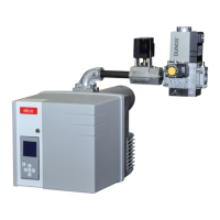
Connect a micro-amperemeter
(0-500µA) instead of the measure
-
ment bridge (check polarity).
•
Press S1/H10.1 - S29J -S2K -
S4 Gas.
•
Switch on the boiler control system.
•
Unlock the control and safety unit.
•
Gas leak test device activates the
burner after a successful check.
•
After the flame has formed, check
the combustion values (CO,CO
2
).
•
Check the UV flow (target value
between 200 and 500 μA).
•
Read the gas flow rate from the gas
counter.
•
Increase the power to high load by
pressing + on the pulsation switch S3.
• Check the exhaust gas values.
Re-adjust the gas/air ratio depending
on the measurement value:
–
with SKP, act on adjustment screw
R. To do this, remove the upper
cover. Higher CO
2
in direction +.
Lower CO
2
in direction -. (see
symbols on the top SKP70 page 34)
–
with MBVEF valve, act on screw V.
Higher CO
2
in direction of greater scale
setting. Lower CO
2
in direction of
smaller scale setting. (see page 34)
•
To achieve the desired level of effi
-
ciency, use the CO
2
and exhaust
gas temperature settings recom
-
mended by the boiler manufacturer.
•
Check the UV flow (target value
between 200 and 500 μA).
•
Read the gas flow rate from the gas
counter.
•
Bring the burner to low load and
check the combustion values.
Depending on the measurement
value, adjust screw D on the SKP
regulator, or screw N on the MBVEF
regulator.
•
Define the desired partial load with
key S3. To do this, re-adjust cam V
as required.
•
Check the exhaust gas values again
and re-adjust the gas/air ratio
depending on the measurement
value.
•
Bring the burner back to full load;
check the combustion values.
• If the measurement values have
changed through the adjustment of
screw D on the SKP regulator or
screw N on the MBVEF valve, the
ratio R on the SKP regulator, or ratio
V on the MBVEF valve must be
adjusted in the desired direction.
m
Dimension Y of the burner head
setting may not be changed.
• If the burner head setting (dimension Y)
is changed, the entire adjustment
procedure for oil operation must be
repeated.
•
Limit switch I may no longer be
changed, as the 3 stage oil has
already been adjusted.
Setting the ignition load
•
Set the ignition load for gas
operation with cam III so that a safe
burner start is guaranteed. Here, the
ignition load can be set above or
below the low load value.
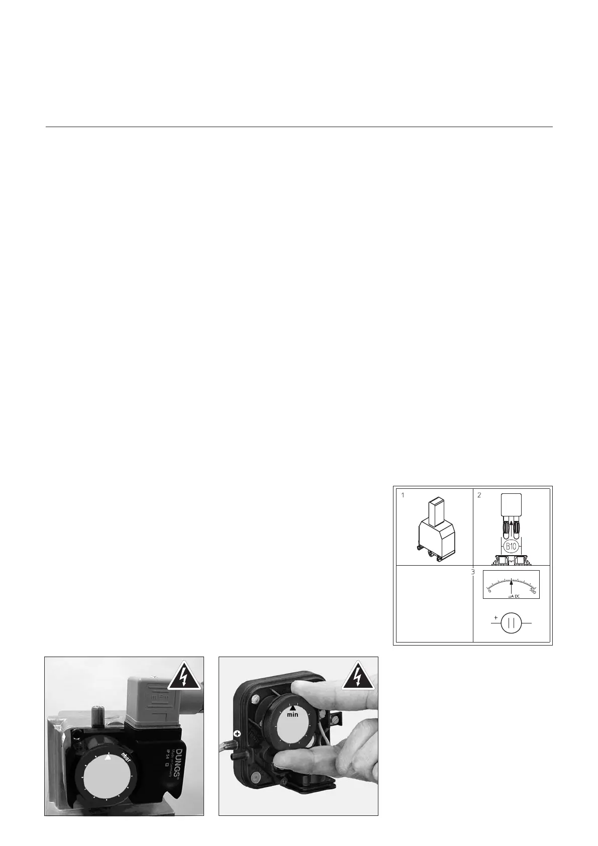
Setting the gas pressure switch
•
Set the switch to the minimum input
pressure.
•
Slowly close the gas shut-off valve.
•
The burner should switch off
because of lack of gas pressure.
•
Re-open the gas shut-off valve.
Setting the air pressure switch
•
Once the burner is again burning at
low load, determine the shut-off
point of the air pressure switch by
turning the scale disk.
•
Set the air pressure switch 10%
below this shut-off value.
Start-up
Regulating the system for gas operation
Setting the gas pressure switch, air pressure switch
 Loading...