06/2011 - Art. Nr. 13 018 118C
34
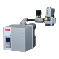
1 Electric supply of the gas
pressure switch (DIN 43650)
2 Electric supply of the magnetic
valves (DIN 43650)
3 Gas pressure switch
4 Input flange
5 Pressure measuring nipple R
1/8, ahead of filter
6 Filter (under cover)
7 Type plate
8 Air pressure conduit connection
pL, R 1/8 (concealed)
9 Setting screw for V ratio
12 Setting screw for zero value N
13 Connection for combustion
chamber pressure release pipe
pF, R 1/8
14 Connection for gas pressure
release pipe pG, R 1/8
15 Output flange
16 Pressure release pipes PBr, pL, pF
pBr (pG) = Gas pressure release pipe
pF = Furnace pressure release pipe
pL = Air pressure release pipe
The SKP regulator combined with a
VGD valve guarantees a constant ratio
between gas and air flow rate with an
adjustable ratio
D = Setting screw (air surplus)
R = Setting screw (ratio Gas/Air)
Function
Gas valve VGD with SKP 75 regulator
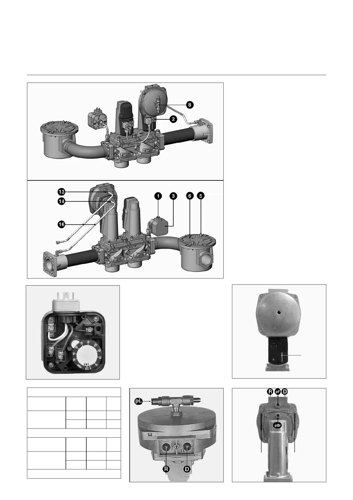
Gas pressure switch setting
•
Remove the transparent cover.
The switch is adjusted via an adjust
-
ment dial with a scale and index x.
•
Set it to the minimum scale value
provisionally.
Burner VGL 06.1200 DP
Gas: pressure (-s)
VGD
Rp2
VGD
DN65
E-Gas: 20, 25
LL-Gas: 20, 25
(Scr R) 1.4 1.3
(Scr D) 22
Burner VGL 06.1600/2100 DP
Gas: pressure (-s)
VGD
DN65
VGD
DN80
E-Gas: 20, 25
LL-Gas: 20, 25
(Scr R) 1.3 1.3
(Scr D) 20
Bold: Default delivery
Display of the
gas valve
Setting index of
the ratio “ R ”
Setting index of
the D value
 Loading...