39
06/2011 - Art. Nr. 13 018 118C
Assembly
Gas valve assembly
Leak test device VPS 504 S01
Assembly of gas valve VGD/MBVEF
•
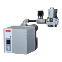
Check the correct installation
location of the O-ring B in the gas
connection flange C.
•
Fix the gas valve with M10 nuts so
that the SKP regulator or the solenoid
of the MBVEF is positioned
vertically above the gas valve.
•
Fit the supplied, labelled pulsation
conduits pF, pL and pG for the left
or right gas connection.
•
With VGD valves, fit the drives
facing upwards, and insert the
supplied gas filter (component) hori
-
zontally with the cover facing
upwards (2 measurement
connections).
•
Note direction of flow.
•
Fit a thermally triggered safety valve
and a gas ball valve (supplied by
manufacturer) before the gas valve.
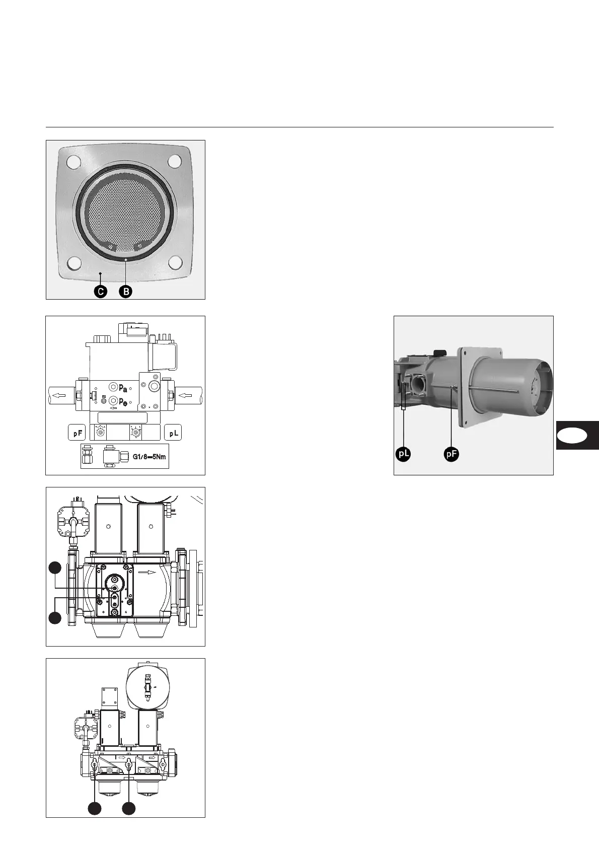
Connection of the gas pressure tube
•
Remove the two stoppers pF and
PL on the intermediate tube.
•
Fit the two connected tube connec
-
tors onto the gas pressure tubes pF
and pL with an approved sealant.
• Create connections between the
valve and intermediate tube for a
right-hand gas valve with the pF
and pL tubes, and with the pF and
pL tubes, labelled “left” for a
left-hand gas valve.
• Check for leaks later.
Installation of the leak test device
VPS 504 S02 on MBVEF/VGD40
•
The two screws pa and pe on valve
MBVEF, and screws 1 and 2 on
valve VGD40 .
•
Ensure that the two O-rings are
present on the leak test device.
•
Secure the VPS504 device with the
four supplied self-tapping screws.
•
Create an electrical connection via
7-pin plugs.
•
Check for leaks.
Installation of leak test device
VPS 504 S02 on VGD20:
•
Remove the two screws 3 and 4
.
•
Screw in a double nipple.
•
Fit the tubing set and connection
adapter.
•
Secure VPS504 and the connection
adapter with the four supplied
self-tapping screws.
•
Ensure that the two O-rings are
present on the leak test device.
•
Create an electrical connection via
7-pin plugs.
•
Check for leaks.
 Loading...