33
06/2011 - Art. Nr. 13 018 118C
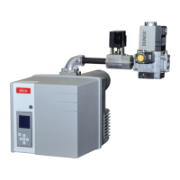
1 Electric supply of the gas
pressure switch (DIN 43650)
2 Electric supply of the magnetic
valves (DIN 43650)
3 Gas pressure switch
4 Input flange
5 Pressure measuring nipple R
1/8 ahead of filter (both sides)
6 Filter (under cover)
7 Type plate
8 Air pressure conduit connection
pL, R 1/8
9 Setting screw for V ratio
10 Pressure measuring nipple pe,
ahead of valve 1, both sides
11 Gas pressure measuring nipple
M4 after valve 2
12 Setting screw for zero value N
13 Connection for combustion
chamber pressure release pipe
pF, R 1/8
14 Connection for gas pressure
take-off pipe pG, R 1/8
15 Output flange
16 Pressure measuring nipple pa
after valve 1, both sides
17 V1 and V2 valve operation
indicator
18 Pressure release pipes
The MBVEF compact gas valve
assembly is a combination of filter,
gas/air regulator, valves and pressure
switches:
–
Fine 0.8 mm mesh filter
–
GWA5 pressure switch
–
Servo-pressure control part with
adjustable ratio V, correction of the
zero point N and combustion
chamber pressure connection.
– V1 and V2 fast-opening and closing
magnetic valves
Input pressure pe: 20-100 mbar
Voltage, Frequency: 230V, 50-60 Hz.
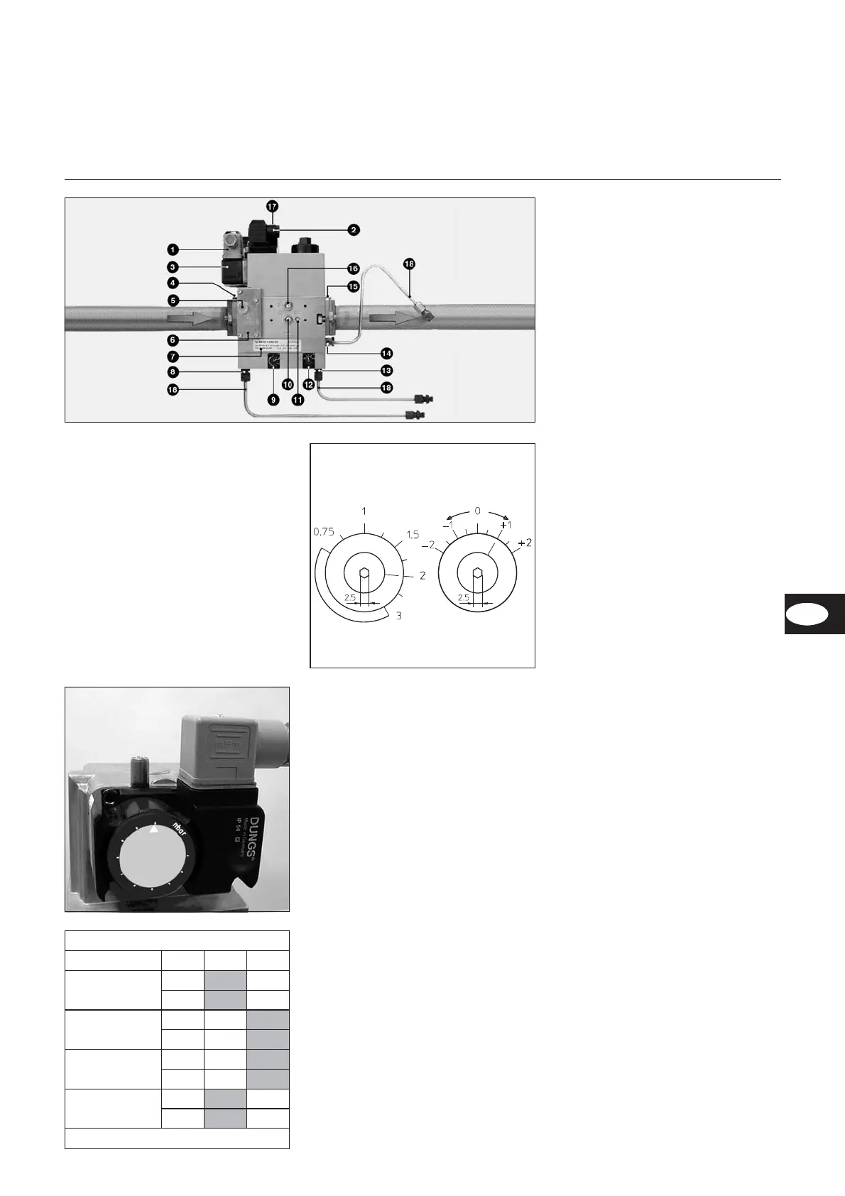
Gas pressure switch setting
•
Remove the transparent cover.
The switch is adjusted via an adjust
-
ment dial with a scale and index x.
•
Set it to the minimum scale value
provisionally.
Burner VGL 06.1600/2100 DP
Gas: pressure (“-e)
VEF
412 420
E-Gas: 20, 25
LL-Gas: 20, 25
V
1.25
N
0
E-Gas : 100
LL-Gas: 100
V
1.25
N
0
F-Gas : 37
V
1.25
N
0
F-Gas: 50
V
1.25
N
0
Bold: Default delivery
Function
Compact valve MBVEF
 Loading...