06/2011 - Art. Nr. 13 018 118C
38
Assembly
Burner assembly
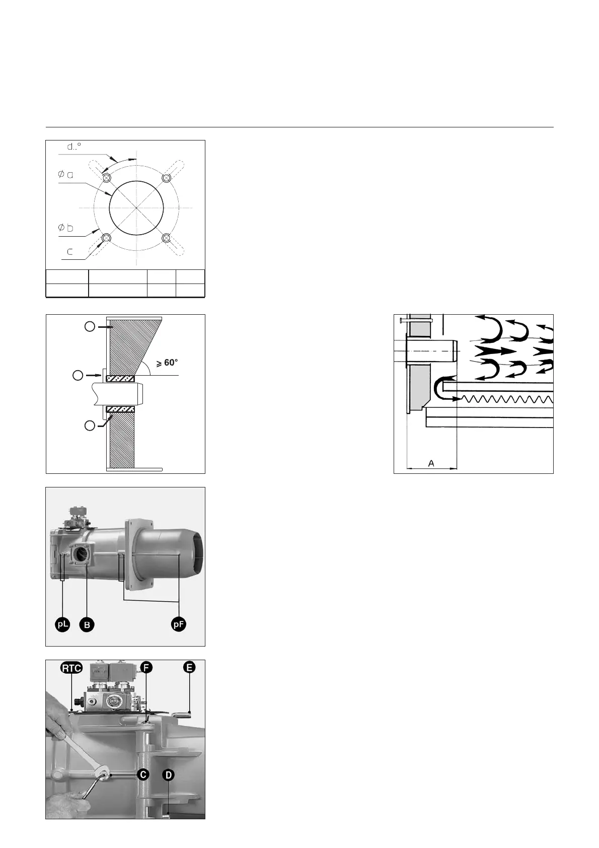
Burner tube insertion depth and
brickwork
On heaters without a cooled front wall,
unless the boiler manufacturer indicates
otherwise, brickwork 5 as shown in the
illustration is required. The brickwork
must not protrude beyond the leading
edge of the blast tube, and should have
a maximum conical angle of 60°. The
space between the brickwork and
burner should be filled with an elastic,
non-inflammable insulation material 6.
On boilers with reverse firing, minimum
insertion depth A of the burner tube
should be observed as per the instruc-
tions of the boiler manufacturer.
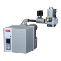
Fitting the burner head
•
Prepare the burner plate/boiler doors
as per the drawing.
•
Stipulate interior diameter a 250 mm.
•
Four M12 holes (300-400 mm
diameter circle) are required, as
indicated in the accompanying
diagram.
•
Screw M12 stay bolts into the
burner plate/boiler door and add the
insulation. If the bolt circle is <400
mm, cut slots to the required size.
•
Fix the burner head with 4
hexagonal nuts M12.
•
The space between the blast tube
and the door insulation must be clad
in fire-resistant material.
N.B.:
Take care not to obstruct the
furnace pressure release pipe, pF.
Fitting the burner housing
If the burner housing hangs below the
burner head axis, proceed as follows:
•
Fix the burner housing to the burner
head using fixed (opposite the gas
connection) axis F.
•
Connect the two ignition cables.
•
Close the burner with axis E.
•
Tighten safety screw D.
The housing can be mounted above
the axis of the burner head if required.
No other positions for the burner
housing are possible.
•
Connecting the oil hose to the oil filter.
•
Connect the oil pressure conduit
from the pump to the oil magnetic
valve block.
•
Check the oil hose connections for leaks.
•
Create an electrical plug-and-socket
connection between the hydraulics
block and the burner.
Ø a (mm) Ø b (mm) c d
250
300 bis 400
M12 45°
 Loading...