SOI/DT 2006-01 dmm 46/71 599 37 47-13
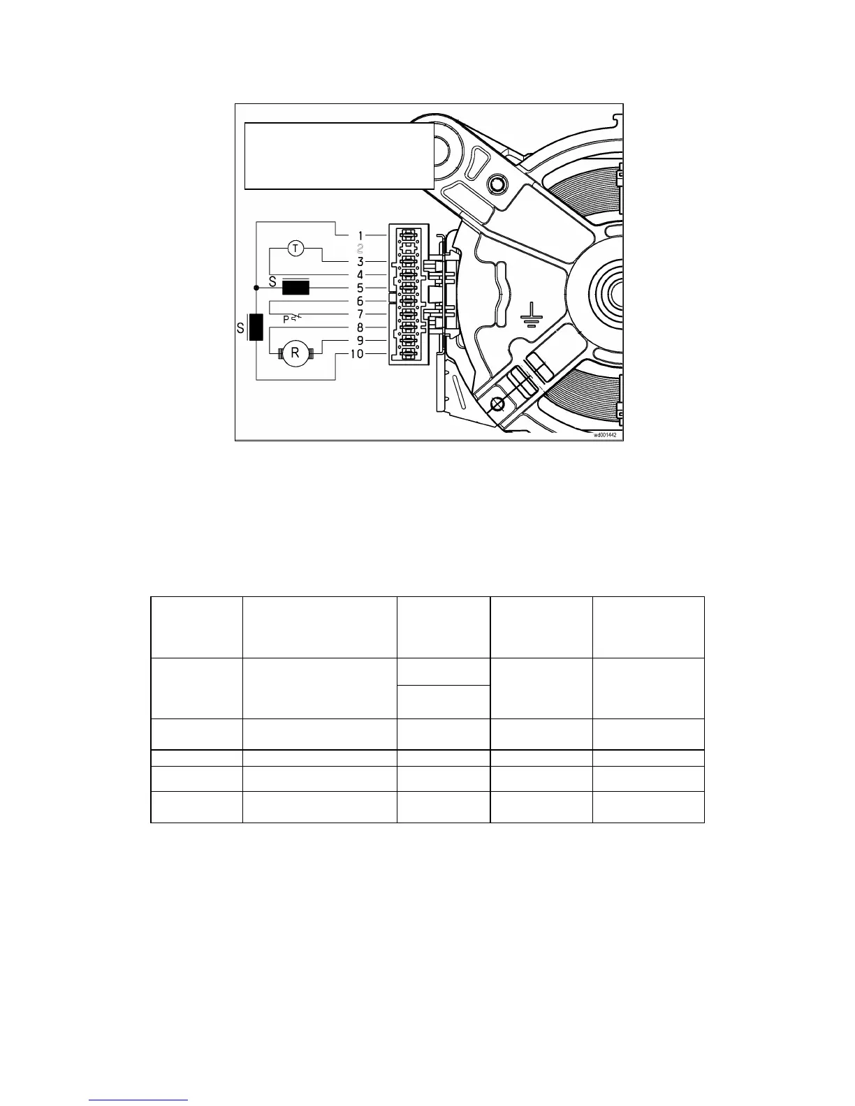
5.8.4 Circuit diagram
5.8.5 Checking for efficiency
1. Check the connector blocks (wiring) and check for any bent or detached terminals.
2. Check for traces / residue / deposits of water or detergent and identify their source.
3. Check for any windings / components connected to mass or inadequately earthed using a tester with a
minimum scale of 40mW across each terminal and the casing (correct reading is ∞).
4. Check the individual windings against the values shown in the table below:
Terminals on
motor
connector
block
Components to be
checked
SOLE ACC
motor
[ Ω]
F.H.P. ACC
motor
[ Ω]
CE.SE.T. motor
[ Ω]
171 ÷ 196
3 - 4
Tachometric generator
winding
469 ÷ 540
126 ÷ 147 64 ÷ 73
5 - 10
Stator winding
(full range)
1.0 ÷ 2.2 1.0 ÷ 3.0 1.0 ÷ 2.0
6 - 7
Overload cut-out 0 0 0
8 - 9
Rotor winding (④) 1.5 ÷ 3.0 1.5 ÷ 3.0 1.5 ÷ 3.0
1 - 10
Stator winding (half range
if terminal 1 is present)
0.5 ÷ 1.0 0.5 ÷ 1.5 0.5 ÷ 1.0
(④) excluding the resistance of the brushes
Notes:
- When checking the rotor winding, measurement should be effected around the entire surface, turning
the spindle very slowly and checking for any short-circuits between visible plates. Also check the carbon
brushes for wear.
- If noise is generated (bearings-magnet-belt), detach the drive belt from the pulleys and locate the
source.
P = Motor overload cut-out
R = Rotor
S = Stator
T = Tachometric generator