SOI/DT 2006-01 dmm 48/71 599 37 47-13
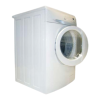
5.10 Inverter (if featured)
The EWM3000 electronic control system uses a new 2-pole, three-phase,
asynchronous motor offering high performance at low noise levels.
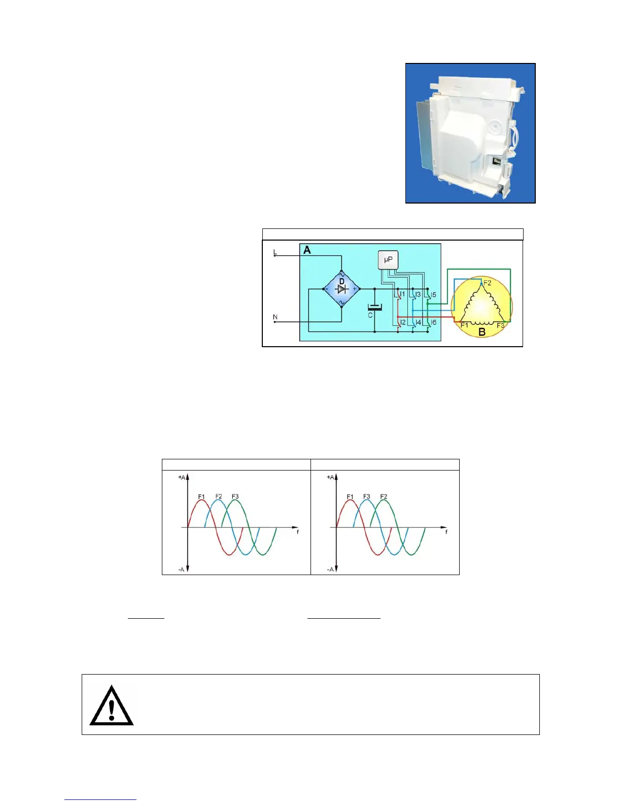
L = Phase
N = Neutral
A = Inverter board
B = Motor
C = Condenser
D = Diodes
I1-6 = Switches
F1-3 = Motor connectors
µP = Microprocessor
A newly designed circuit board (A) is used to convert single-phase power (available in homes) into three-
phase power. The amplitude and frequency of the three-phase power can be varied to adjust motor power
and RPM, respectively.
Single-phase power (applied to connectors L-N) is rectified by a diode bridge (D) to generate 310 VDC at
the poles of condenser C. The combined opening and closing of switches I1-I6 (this switching is performed
by the microprocessor) determines the voltage and frequency of the power applied to the motor.
Clockwise motor operation Counter-clockwise operation
Motor speed is controlled using the signal from a tachometric generator (T).
During spin phases, the microprocessor may perform (depending on the configuration of the software)
checks for antifoam
(if available on the machine) and anti-unbalancing.
The electrical components must be serviced by qualified personnel only.
Unplug the appliance before accessing internal components.
“INVERTER” Electric wiring