MP500/4N-8-16 Installation
1.2 SYSTEM ARCHITECTURE
1.2.1 Architecture
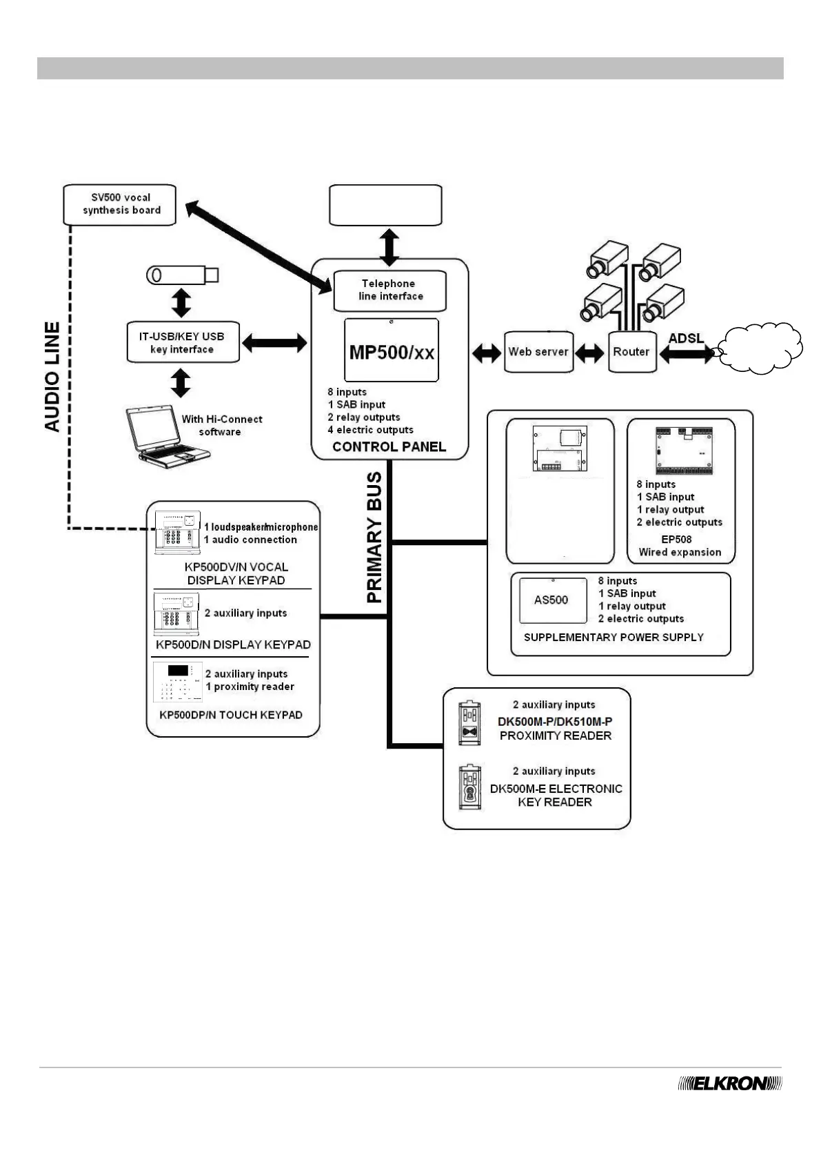
The diagram illustrates the devices and connections that can eventually be managed by the MP500/4N, MP500/8 and MP500/16
control panels. For the maximum dimensions the system can reach (combinations of devices and their maximum number) see the
paragraph 1.2.3 Maximum system size.
Figure 1 - System Architecture of the MP500/4N - MP500/8 - MP500/16
1.2.2 Bus Data
Control panel, keypads, readers, expansion modules and radio modules are interconnected by a 4-wire bus.
The 4 wires transmit information among the various devices and supply 12 V⎓ power from the MP500/4N, MP500/8 or MP500/16
control panel to the keypad, readers, expansion modules, and radio modules.
The use of the bus noticeably simplifies the wiring, given that, for example, the information of a group of detectors located far from the
control panel and concentrated on a remote EP508 expansion module can be controlled with just 4 wires.
Radio Expans.
For details,
refer to the
dedicated
manual
Notes:
* MP500/4N control panel = 4 inputs,1 SAB input,
1 relay output,1 electric output
**= not available in the MP500/4N control panel.
***= not present in the KP500D/ST keypad.