MP500/4N-8-16 Installation
5.5 INSTALLING THE MP500/4N - MP500/8 - MP500/16 CONTROL PANELS
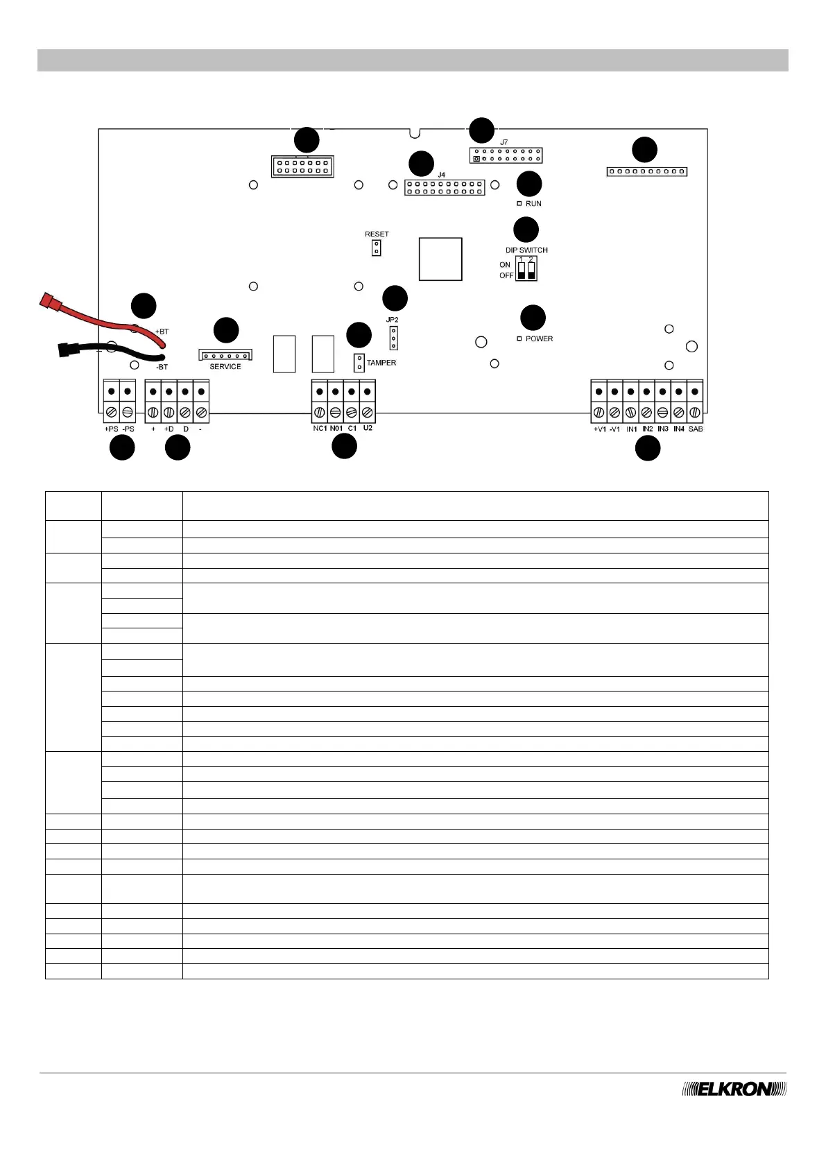
5.5.1 Description of the main parts of the MP500/4N control panel
Figure 31 - Connections and main parts of the MP500/4N control panel
Input +14.4 V⎓ power supply (at the positive pole of the power supply)
Input power supply (at the negative pole of the power supply)
Connection positive pole of the back-up battery
Connection negative pole of the back-up battery
BUS Power supply (13.8 V⎓ limited to 1.1A ) for devices connected via bus
BUS Data transmission/reception
Power supply of the detectors connected to the control panel (13.8 V⎓ limited to 750 mA).
The mother board has two pairs of power supply terminals.
Input 24h (for system self-protection). It must always be BALANCED and closed with a 15 kΩ balancing resistor.
Relay output 1 – contact normally closed
Relay output 1 – contact normally open
Relay output 1 – common (max. 1 A - 24 V⎓)
Electric output 2 (current protected max. 100 mA)
Connector for ILT500-N PSTN communicator
Green LED to signal functioning of the control panel (see paragraph 6.1.1 RUN LED Indications).
Green LED for signaling mains presence
Connector of the USB and Web server interface
Dip-switch to reset parameter – see functions associated with the dip-switches (Table 6)
(normally they must be left OFF)
Connector of the vocal synthesis board
Connector for connection of the control panel tamper
Jumper configuration output U2
Connector for connecting the service keypad
Connector for IMG500/N GSM Module (connecting point on the rear side of the motherboard)
 Loading...