MP500/4N-8-16 Installation
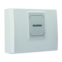
The electric outputs U3, U4, U5 and U6 can be individually configured as “Positive Reference” or “Negative Reference” via the JP3,
JP4, JP5 and JP6 jumpers. The factory setting of the outputs is “Positive Reference”.
The electric outputs can be transformed into relay outputs – See Paragraph 5.12.6.2.
The figure illustrates how to position, for example, the JP3 jumper.
Figure 34 - Configuration of the electric output hardware
Functions associated do the DIP-switches
To activate the reset functions associated with the DIP-switches, it is necessary to follow the indications found in paragraphs 7.9.4
Resetting hardware installer code and 7.9.5 Resetting hardware to factory settings.
Reset hardware factory settings
*= if positioned on ON before “POWER ON”
Table 7 - Functions associated with the DIP-switches of the mother board
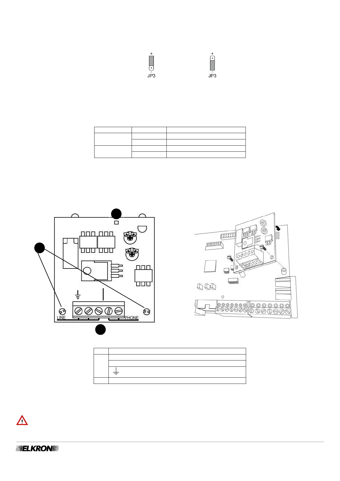
5.5.3 Assembly of the PSTN ILT500-N communicator
Figure 35 - Assembling PSTN communicator board
LINE PSTN Input telephone line
PHONE PSTN Input telephone line
Yellow LED signals that the telephone line is engaged
To assemble the PSTN communicator board follow the instructions below:
Insert the two support spacers included in the 2 holes (A) of the board.
Insert the header connector in the special connector (F) of the mother board.
Tighten the plastic nuts included to the support spacers through the holes present on the mother board.
IMPORTANT! The connection and disconnection of the optionals and accessories must always be done while the control
panel is disconnected from all power supplies (both mains and battery).