MP500/4N-8-16 Installation
5.4.2 Openings for cables
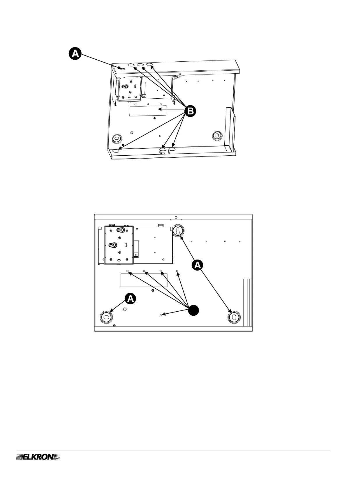
The figure below illustrates the hole for the optional GSM antenna (A) and all the set-up (B) for running the power supply, bus,
signalling detector and device, potential telephone line cables of the MP500/16 control panel.
Figure 25 - Set-up for running cables and fastening the GSM antenna MP500/16
5.4.3 Fastening to the wall
The figure illustrates the holes available for fastening the control panel to the wall. Use the 8 mm expansion screws suitable to the
type of wall (for this step, consult qualified personnel).
Figure 26 - Holes for fastening the MP500/16
The set-up for running the cables are:
A - for embedded corrugated tube;
F – points for anchoring cables with bands.
 Loading...