MP500/4N-8-16 Installation
5.7 INSTALLATION OF THE EP508 EXPANSION
In addition to inside the control panel, the EP508 expansion can also be installed inside a CP/EXP container (certified Grade 3) or a
CP/EP500 container (not certified).
IMPORTANT! the absence of a casing certified Grade 2 or 3 results in the loss of certification.
The tamper of the container must be connected to the SAB of the expansion.
The expansion has terminals for connecting the power supply, detectors, ad signalling devices, etc.
The electric outputs can be transformed into relay outputs – See Paragraph 5.12.6.2.
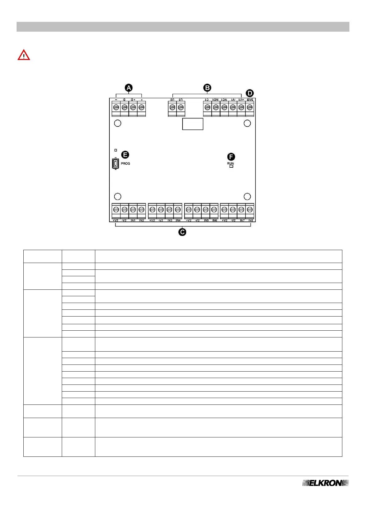
Figure 45 - EP508 Expansion
BUS Expansion unit power input via bus
BUS Data transmission / reception
BUS Expansion unit power input via bus
Power supply for output actuators (13.2 V⎓ limited to 500 mA)
Relay output 1 – contact normally closed
Relay output 1 – contact normally open
Relay output 1 – common (max. 1 A - 24 V⎓)
Electric output 2 (current protected max. 10 mA)
Electric output 3 (current protected max. 10 mA)
Power to detectors connected to expansion unit (13.2 V⎓ limited to 500 mA).
Four pairs of power terminals are connected to the expansion unit.
Input 24h (for system self-protection). It must always be BALANCED and closed with a 15 kΩ
balancing resistor
Device acquisition button and LED
Green LED signals operating (for details see the Programming Manual)
Slow blinking = normal operating conditions
Fast blinking = no communication with control panel for at least 1 minute
For details on connections (power supplies, inputs, outputs, bus, etc. …) see paragraph 5.12.2 Connecting the data Bus and
paragraphs, 5.12.5 Connecting inputs and 5.12.6 Connecting outputs.