MP500/4N-8-16 Installation
3. Open the keypad by putting a screwdriver into the slot on the lower side and lifting gently.
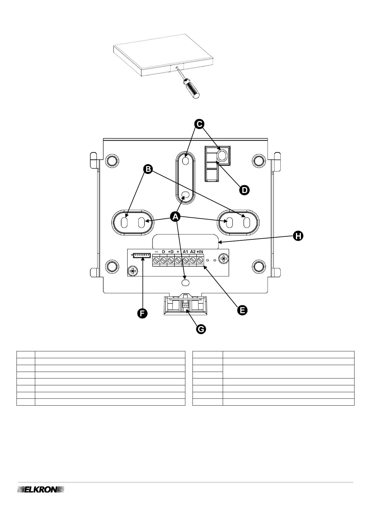
Figure 50 - Opening the KP500DP/N - KP500D/ST keypad
Figure 51 - Holes for fastening and running the cables of the KP500DP/N - KP500D/ST keypad
Holes for fastening onto the Ø 60 mm built-in box
Holes for fastening to 3-place box
BUS Expansion unit power input via bus
Holes for removal protection screws
BUS Data transmission/reception
Plastic insert for anti-removal protection
Connection terminal board
BUS keypad power supply via bus
Power supply for auxiliary inputs
4. To use the anti-removal device, put an expansion screw in hole “C” and fasten it to block “D”. For EN50131 Degree 3 certification, it
must always be used, even if the keypad is fixed to a flush-mounting box. This requirement is not mandatory for Degree 2 or lower
installations.
5. Connect the bus cable to the terminal board. For details of the connection, see paragraph 5.12.2 Connecting the data Bus.
6. Insert the small cable coming out of the keypad in the dedicated connector “F”. Place the cable so that it fits into the specially
designed space at the bottom of the keypad; this prevents it from being crimped when assembling the keypad to the bracket.
7. Insert the keypad block into the bracket and slide it downward.
8. Block it with a fastening screw “G”.