8
English
BASIC
OPERATIONS
②
To connect the unit to a device with an analog RGB input terminal.
Connect the RGB cable to the [
RGB OUT
] terminal on the rear panel.
Only 1 RGB cable is supplied with the product.
③
To connect the unit to a device with an analog RGB output terminal.
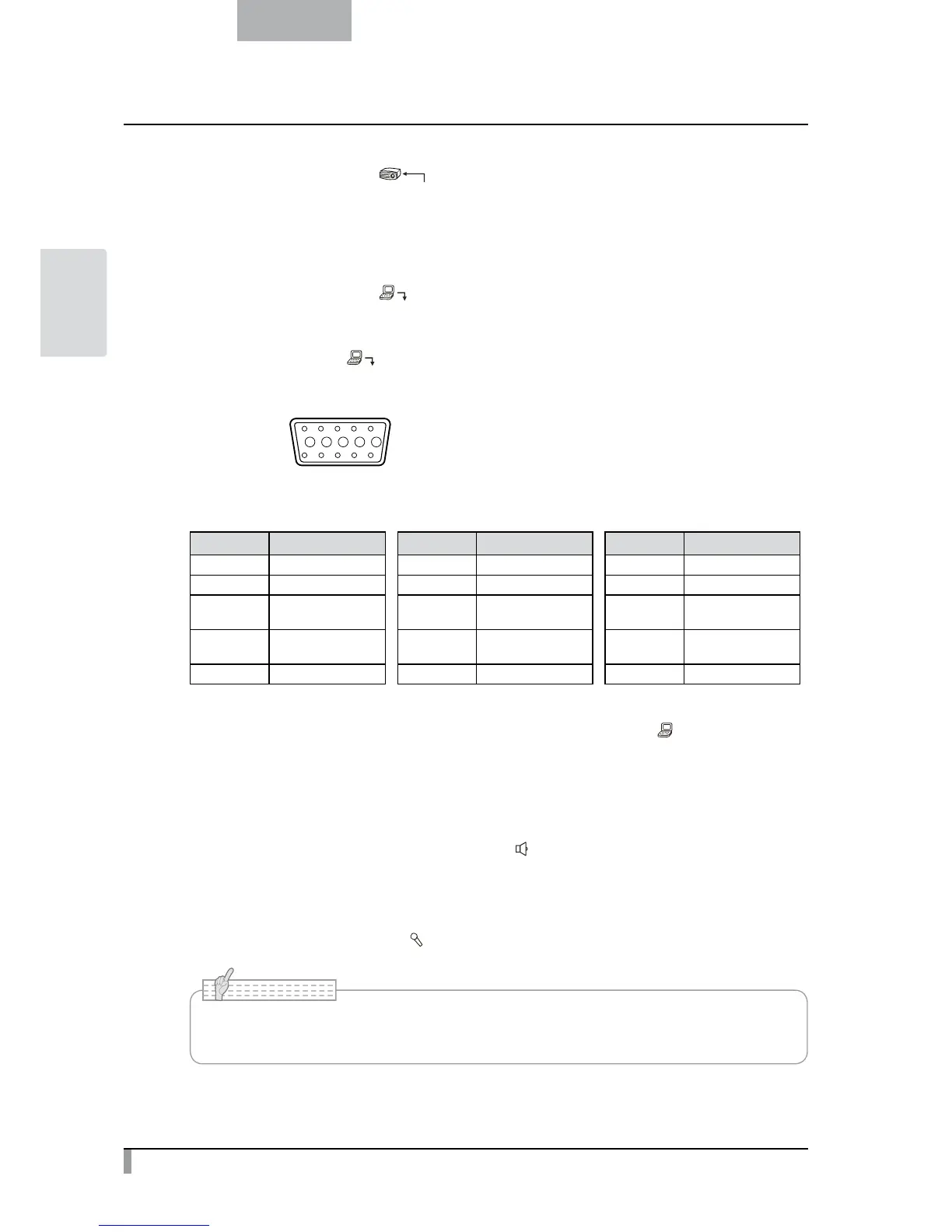
Connect the RGB cable to the [
15 14 13
DSUB 15P shrink terminal (Female)
12 11
Video signal
Horizontal synchronized signal
Vertical synchronized signal
Analog 0.7V (p-p) 75Ω terminated
TTL level (Positive/negative polarity)
TTL level (Positive/negative polarity)
Pin assignment
Pin No. Name Pin No. Name Pin No. Name
1 Video signal (Red) 6 GND (Red) 11 GND
2 Video signal (Green) 7 GND (Green) 12 N.C
3 Video signal (Blue) 8 GND (Blue) 13
Horizontal
synchronized signal
4 N.C 9 N.C 14
Vertical
synchronized signal
5 GND 10 GND 15 N.C
④
To connect the unit to a device with an RS-232C port.
The
unit can be controlled from a PC through an RS-232C cable by using [
RS-232C
] terminal on the rear
panel.
⑤
To connect the unit to a device (speaker with amplifire etc) with an audio line input terminal.
Connect a commercially available audio cable to the [
AUDIO OUT
] terminal on the rear panel.
⑥
For connecting to a device equipped with an external mic. / audio line output terminal.
Connect an external microphone to [
MIC
] terminal on the rear panel.
• Do not use any microphone other than an electret condenser microphone (such as a PC
microphone). Otherwise, the unit may be damaged.
N o t e