12 11
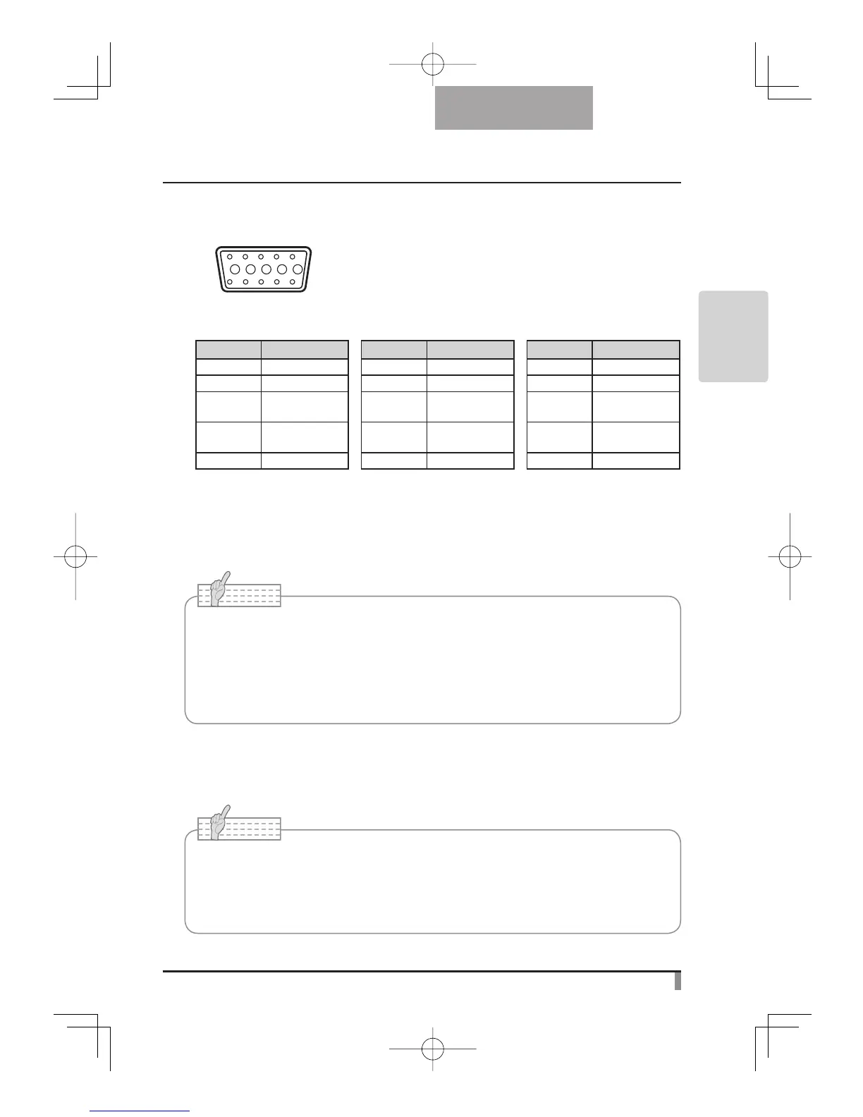
Video signal :
Horizontal synchronized signal :
Vertical synchronized signal :
Analog 0.7V(p-p) with 75Ω terminated
TTL level (Positive/negative polarity)
TTL level (Positive/negative polarity)
Pin assignment
Pin No. Name Pin No. Name Pin No. Name
1
Video signal (Red)
6 GND (Red) 11 GND
2
Video signal (Green)
7 GND (Green) 12 N.C
3
Video signal (Blue)
8 GND (Blue) 13 Horizontal
sync. signal
4 N.C 9 N.C 14 Vertical
sync. signal
5 GND 10 GND 15 N.C
(3) Connecting to the unit with composite video input terminal equipped
Connect the video cable with RCA pin plug to the [VIDEO OUT] terminal on the rear panel.
(4) Connecting to the PC with a USB cable
Connect a USB cable to the [USB] terminal on the rear panel.
(5) Connecting the AC adapter
Connect the DC plug of the supplied AC adapter to the [DC IN 12V] terminal on the rear
panel before inserting the AC adapter in an outlet.
Note
• As for switching-over of the image output, refer to “OUTPUT (DIP switch)” on page 12.
• To protect the unit and peripheral devices, unplug the power plug and the AC adapter,
turn OFF power switches of all other devices before connecting video cable.
• Hold the plug of cable to plug/unplug the power plug/the AC adapter or video cable.
Note
• The USB cable compliant with USB2.0 is recommended.
• If you plug into a USB connector with power on, PC may not recognize this product.
• Depending on the USB environment of PC or the USB2.0 compliant cable is
recommended. Peripheral units, the image transfer may be disturbed.
• This does not guarantee operations in any environment.
 Loading...