23
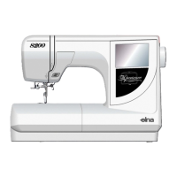
Model 8300
8
1
2
3
4
5
6
7
9
10
11
1213
1415
16
17
18
19
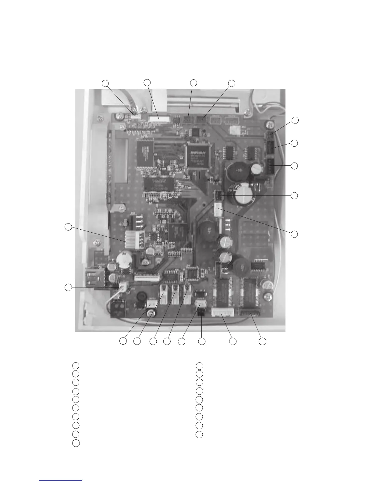
Connector Connection Diagram
Please see the following connector connection diagram for the printed circuit board A.
Touch panel
LCD Harness
Presser foot lifter sensor (Red)
Thread detection sensor ( Red )
Bobbin winder sensor (Black)
Upper shaft sensor (Black)
Printed circuit board F (Black)
Remaining bobbin thread sensor (Blue)
Switching power supply ( White )
X- Motor ( Blue )
Y- Motor (White)
Thread cutter switch (Black)
Thread cutter solenoid (Red)
Solenoid for thread tension (Red)
Remaining bobbin thread solenoid (Blue)
Lamp (White)
Needle thread solenoid (White)
Inverter (White)
DC Motor (White)
8
1
2
3
4
5
6
7
9
10
11
12
13
14
15
16
17
18
19