7
Model 8300
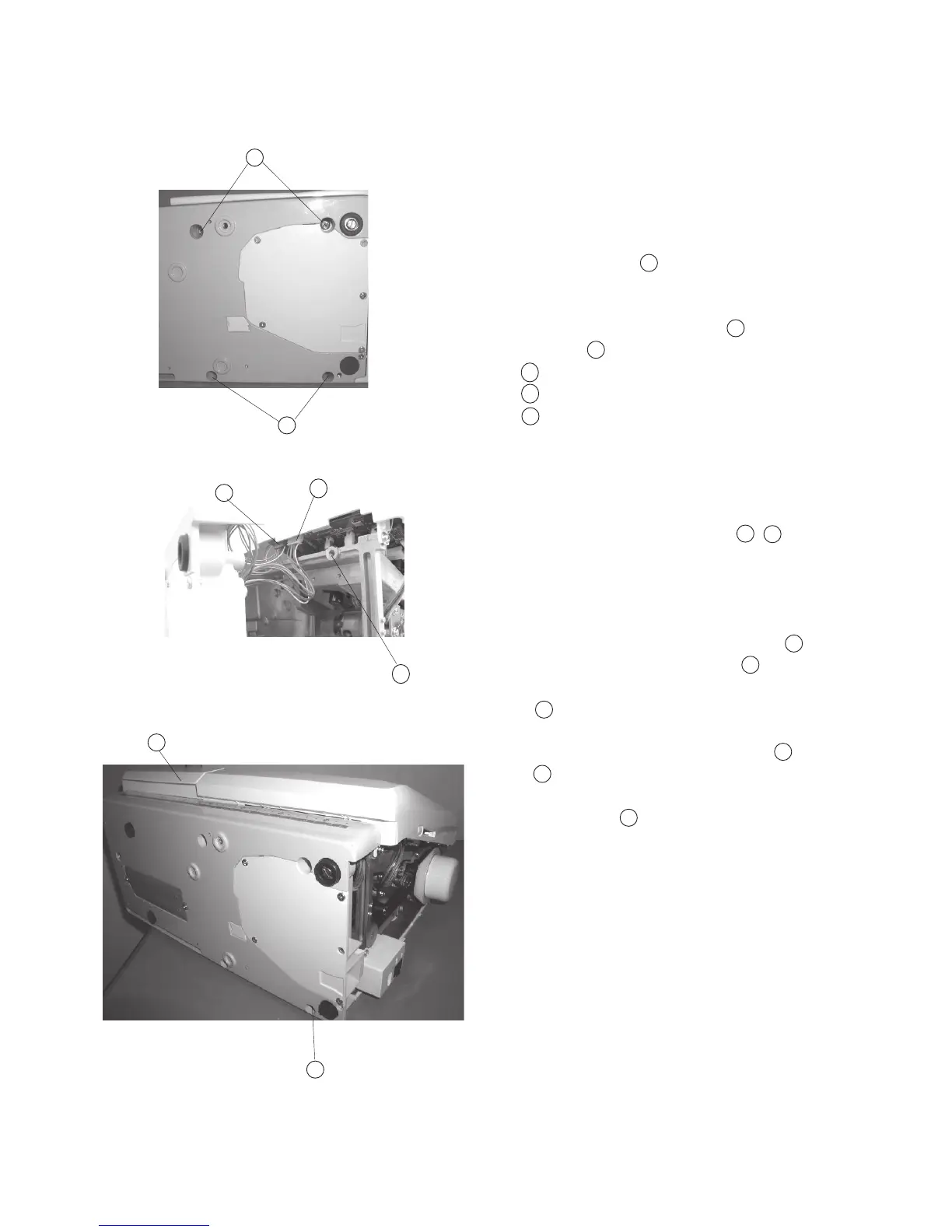
Changing External Parts (5) Base Unit
Base
To remove:
1. Remove the Belt cover. (See page 4)
2. Remove Setscrew (4 pcs.), and remove
the base unit .
3. Remove the X-Motor Connector and Y-Motor
Connector from the printed circuit board “A”.
Joint bosses
Y-motor connector (White)
X-motor connector (Blue)
To attach:
4. Attach the X, Y-Motor Connectors , into
the printed circuit board “A”.
5. Insert the X, Y-Motor Cords between the printed
cuircuit board “A” and Arm. Be sure the cords
are not caught between the Joint Bosses of
the arm and base. Tighten Screws (4 pieces)
temporarily.
Joint boss
6. Attach the Extension (Accessory) table .
Extension table (Accessory)
7. Tighten Screws while aligning the extension
table, base unit and free Arm.
Note: Attach the embroidery hoop with the template
on the carriage. Check the needle drop posi
tion against the template.
8. Attach the belt cover.
A
9
8
B
8
9
A
A
8
9
B
8
9
B
A
B
C
C
A
C
A