Home
Elster
Measuring Instruments
EK280
Page 30 (4 Construction and Function)
Elster EK280 - 4 Construction and Function; 4.1 External view; 4.2 Internal view
119 pages
Manual
Save Page as PDF
To Next Page
To Next Page
To Previous Page
To Previous Page
Loading...
30
Construction and Fu
nction
4 Construction and Function
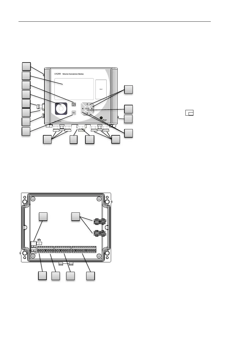
4.1
External view
Fig. 4
1
Display
2
Cable bushings f
or the
connection of additi
onal
components
3
Optical interface
4
Escape button "ESC
"
5
Enter button "ENT
ER"
6
Function ke
y
7
Arrow keys
,
,
,
8
Pressure sensor
9
Cable bushing
Temperature sensor
10
Earth connect
ion
11
Sealing e
yelets
12
Outdoor plug (op
tional)
13
Cable bushin
g
Aerial
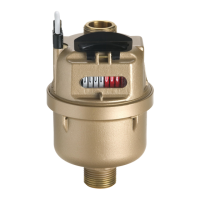
4.2
Internal view
X
1
4
X
1
0
X
1
1
X9
-
+
X8
Fig. 5
1
Connections for tem
perature
and pressure sensors
2
Connections for c
ounting and
signal inputs "D
E1" to "DE6"
3
Connections for pulse
and sig-
nal outputs "DA1" to
"DA4"
4
Connections for s
erial inter-
faces
5
Connections for ex
ternal pow-
er supply "Uext"
6
Connections for batteri
es
Instromet
Identification
la
bel
1
6
3
8
9
10
4
5
7
2
2
12
13
7
11
11
6
5
4
3
2
1
29
31
Table of Contents
Main Page
Default Chapter
3
Table of Contents
3
1 General
7
Information about this Manual
7
Warranty Provisions
7
Customer Service
7
Customer Service and Repairs
7
Electronic Hotline
8
Meaning of Symbols
8
Safety Information
8
Tips and Recommendations
9
Limitationof Liability
9
Copyright Protection
9
Scope of Delivery
10
Spare Parts and Accessories
10
Storage
11
2 Safety
12
General
12
Intended Use
14
Personnel
15
Personal Protective Equipment
16
Specific Risks
17
Environmental Protection
18
Operator's Responsibility
18
3 Technical Data
20
General Data
20
Power Supply for EK280 Without Integrated Power Supply Unit
20
Battery Power Supply for the Basic Device
20
Battery Power Supply for the Integrated Modem
20
External Power Supply for the Basic Device
21
Power Supply for EK280 with Integrated Power Supply Unit
21
Battery Power Supply for the Basic Device
21
External Power Supply
21
Buffer Batteries for the Integrated Modem
21
Pressure Sensor
22
CT30 Type Pressure Sensor
22
Pressure Sensor Type 17002
23
Temperature Sensor
23
Digital Inputs
23
LF Pulse and Signalinputs
23
HF Pulse Inputs (High Frequency)
24
Encoder Input
24
Digital Outputs
25
Nominal Data
25
LF Pulse or Signal Outputs
25
HF Pulse Outputs
25
Interfaces
26
Serial Optical Interface
26
Serial Electrical Interface
26
Integrated Modem
26
Measurement Conditions
27
Environment
27
Labeling
27
Type Label of the Volume Corrector
27
ATEX Marking
28
Device Software Identification
29
4 Construction and Function
30
External View
30
Internal View
30
Short Description
31
Connections
31
5 Assembly, Connection and Putting into Operation
32
Assembly
32
Assembly on a Gas Meter
33
Assembly on a Pipeline
33
Assembly on a Wall
34
Three-Way Valve
34
Connection
35
Connecting the Gas Meter
36
Sealing the Input Terminals
38
Connecting the Temperature Sensor
38
Connecting the Pressure Pipe
40
Connecting the Power Supply
41
Connect Outputs of the EK280
43
Earthing the EK280 Housing
44
Earthing the Cable Connections of the EK280
45
Additional Measures for Installation in Zone 2
45
Putting into Operation
46
Configuration of Measurement Parameters
46
Sealing
55
Closing the Housing
57
Verifying Assembly and Connection
57
6 Operation
58
Safety
58
Personal Protective Equipment
58
Operating Personnel
58
Instructed Personnel
58
Qualified Personnel
58
Calibration Officers
59
Basic Principles
59
Display
60
Button Functions
61
Data Recall, Display Navigation
62
Meaning of Status Symbols
63
Error Messages When Entering Values
65
Access Rights
66
Data Register Content
68
Access Rights
68
Main" Register (Main Display)
68
Cust." Register (Customer)
70
Admin" Register (Administrator)
72
Serv." Register (Service)
73
Ctrl." Register (Control)
74
7 Maintenance
77
Safety
77
Personnel
79
Personal Protective Equipment
79
Environmental Protection
79
Testing and Changing Device Batteries
80
Changing and Connecting Device Batteries
80
Entering the Battery Capacity
82
Display Remaining Battery Power
83
8 Faults
84
Safety
84
Personnel
84
Personal Protective Equipment
85
Improper Elimination of Faults
85
Behavior in the Event of Faults
85
Fault and Other Status Messages
86
9 Appendix
91
List of Spare Parts and Accessories
91
Fastening Elements
91
Pressure Connections
91
Temperature Sensor Pockets
92
Small Parts and Miscellaneous
92
Documentation
92
EC Declaration of Conformity
93
ATEX Type Examination Certificate
94
Zone 1
94
Zone 2
109
Other manuals for Elster EK280
Applications Manual
163 pages
Related product manuals
Elster EK260
126 pages
Elster V100
8 pages
Elster A100C
50 pages
Elster A1140
157 pages
Elster A1120
157 pages
Elster BK-G25
10 pages
Elster A3 ALPHA
4 pages
Elster 6 Series
68 pages
Elster BK-G Series
10 pages
Elster ALPHA A1800
20 pages
Elster Q.Sonic PLUS
68 pages
Elster DE-07-MI004-PTB025
40 pages