Assembly, Connection and Putting into Operation 33
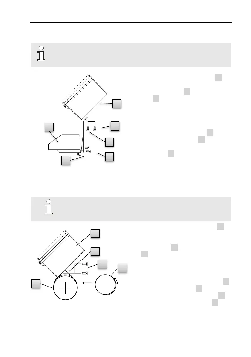
5.1.1 Assembly on a gas meter
Mount the EK280 on a gas meter using a mounting bracket
(see Appendix) as well as the corresponding cylinder screws
and square nuts.
1. Using two M5 x 10 mm (Fig. 6: 4 )
cylinder screws, attach the mount-
ing bracket (Fig. 6: 6 ) to the EK280
(Fig. 6: 1 ).
2. Tighten the cylinder screws so that
the bracket is sitting in a fixed posi-
tion.
3. Attach the mounting bracket using
two square nuts M5 (Fig. 6: 7 ) and
two M5 x 10 mm (Fig. 6: 5 ) cylin-
der screws at the back of the meter
head (Fig. 6: 8 ).
4. Tighten the cylinder screws so that
the device is in a fixed position and
cannot fall down.
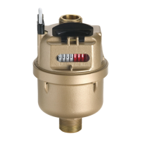
5.1.2 Assembly on a pipeline
Mount the EK280 to a pipeline using an A2 universal
bracket with a pipe clamp (see Appendix) as well as corre-
sponding cylinder screws.
1. Using two M5 x 10 mm (Fig. 7: i1i)
cylinder screws, insert the A2 uni-
versal bracket in the boreholes pro-
vided (Fig. 7: i3 ) on the EK280 (Fig.
7: i2 ).
2. Tighten the cylinder screws so that
the bracket is sitting in a fixed posi-
tion.
3. The A2 universal bracket (Fig. 7: i3 )
and the device (Fig. 7: i2 ) should be
fastened to the pipeline (Fig. 7: i5 )
using the pipe clamp (Fig. 7: i4 )
4. The device should be mounted on the pipeline in such a way that it is in a
fixed position and cannot fall down.