36 Assembly, Connection and Putting into Operation
Connect unused cable glands as per DIN EN 60079-14 with the help of
a plug or a suitable screw cap.
In order to program the device and perform further applications, and in ad-
dition to the components specified in this chapter, you can also connect an
external power supply to the other connections as well as the serial and op-
tical interface of the EK280 (see "Construction and Function" chapter). Fur-
ther details can be found under www.elster-instromet.com.
The connections described below should only be sealed by
a calibration officer. If the EK280 is used for operations
which are not subject to calibration regulations, the seals on
the respective connections can be omitted.
5.2.1 Connecting the gas meter
In order to measure the gas volume, a gas meter with a low or high fre-
quency pulse transducer or encoder can be connected to the digital input
"DE1" of the EK280.
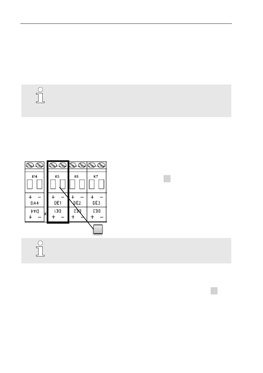
The pulse transducer or encoder of the
gas meter will be connected to the
"DE1" terminal ( 1 ) of the EK280.
Further details and special features re-
garding the use of the pulse transducer
and encoder are described in the follow-
ing sub-chapters.
The cable core diameter for the connection to the EK280
inputs is
0.33 … 2.5 mm
2
.
5.2.1.1 Connection to a low frequency pulse transducer
1. Connect the pulse output of the gas meter to the "DE1" terminal ( 1 in
Fig. 10, page 36) of the EK280.
The polarity can be freely selected (the symbols "+" and "-" on the ter-
minals are used for the connection of other pulse transducers or encod-
ers).
2. Adjust the measurement parameters, e.g. the cp value (pulse constant),
as described in chapter 5.3.1.3 .