Rosemount Model 1195/ProPlate/Mass ProPlate
2-20
Perform the following procedure to install adapters to the 1195 Integral
Orifice process connections:
1. Place non-threaded side facing 1195 process connections. This will
leave thread side facing transmitter.
2. Install and tighten bolts and tighten bolts and nuts. Refer to
“Mounting Bolts” on page 2-26 for torque specifications.
When compressed, Teflon
®
(PTFE) O-rings tend to cold flow, which aids
in their sealing capabilities. Whenever you remove flanges or adapters,
visually inspect the Teflon O-rings. Replace them if there are any signs
of damage, such as nicks or cuts. If they are undamaged, you may reuse
them. If the you replace the O-rings, re-torque the flange bolts after
installation to compensate for cold flow. Refer to the process sensor body
reassembly procedure in Section 9: Troubleshooting.
Valves and Fittings Throughout the remote mounting process:
• Use only valves and fittings rated for the service pipeline design
pressure and temperature as specified in Section 10:
Specifications and Reference Data.
• Use a pipe thread sealant compound that is rated for use at the
service temperature and pressure for all valves and fittings.
• Verify that all connections are tight and that all instrument
valves are fully closed.
• Verify that the meter assembly is properly oriented for the
intended type of service: liquid, gas or steam (see Figures 2-23,
2-24, and 2-25).
Impulse Piping A remote mounted electronics is connected to the sensor by means of
impulse piping. Temperatures in excess of 450°F at the electronics
will damage electronics components; impulse piping allows service
flow temperatures to decrease to a point where the electronics is no
longer vulnerable.
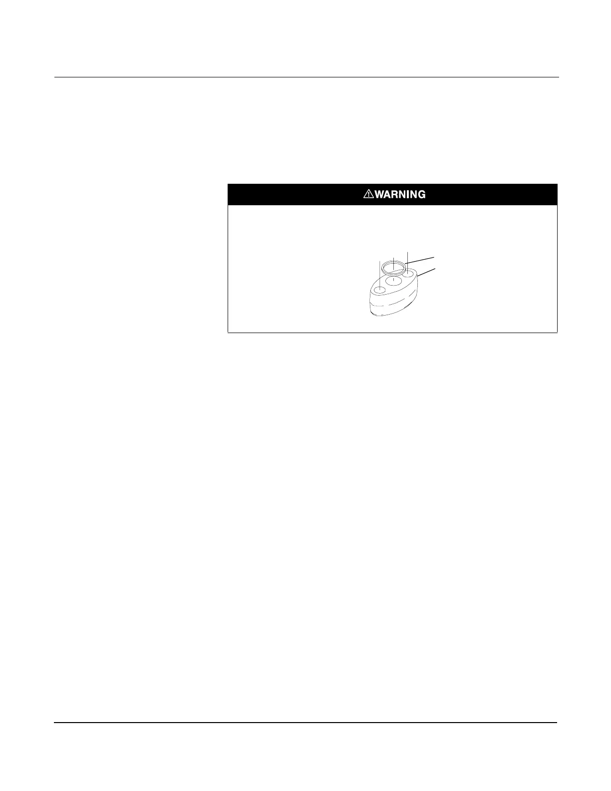
Failure to install proper flange adapter O-rings can cause process leaks, which can
result in death or serious injury.
The flange adapters require a unique O-ring, as shown below.
Unique O-ring Grooves
Flange Adapter
O-ring

 Loading...


