30
Reference Manual
00809-0100-4772, Rev FA
Installation
March 2016
Installation
Note
A grounding strap is specifically required if using the transient protection terminal block
(Option Code T1). Always ground the meter per the local electrical code.
3.5.4 Flange bolts
Install the flowmeter between two conventional pipe flanges, as shown in Figure 3-12 and
Figure 3-13 on page 33. Figure 3-6, Figure 3-2, and Figure 3-3 list the recommended
minimum stud bolt lengths for wafer-style meter body size and different flange ratings.
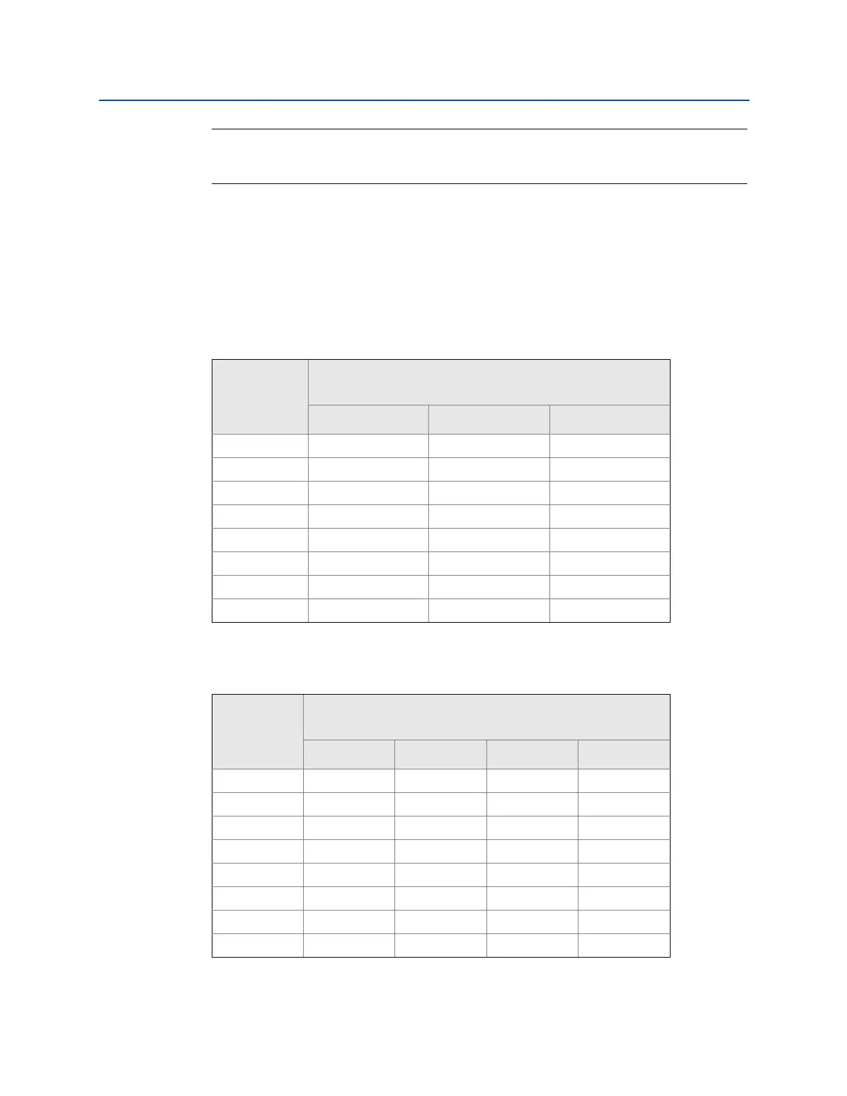
Table 3-1. Minimum Recommended Stud Bolt Lengths for Wafer Installation with
ASME B16.5 (ANSI) Flanges
Table 3-2. Minimum Recommended Stud Bolt Lengths for Wafer Installation with DIN
Flanges
Line size
Minimum recommended stud bolt lengths
(in Inches) for each flange rating
Class 150 Class 300 Class 600
½-inch 6.00 6.25 6.25
1-inch 6.25 7.00 7.50
1½-inch 7.25 8.50 9.00
2-inch 8.50 8.75 9.50
3-inch 9.00 10.00 10.50
4-inch 9.50 10.75 12.25
6-inch 10.75 11.50 14.00
8-inch 12.75 14.50 16.75
Line size
Minimum recommended stud bolt lengths
(in mm) for each flange rating
PN 16 PN 40 PN 64 PN 100
DN 15 160 160 170 170
DN 25 160 160 200 200
DN 40 200 200 230 230
DN 50 220 220 250 270
DN 80 230 230 260 280
DN 100 240 260 290 310
DN 150 270 300 330 350
DN 200 320 360 400 420

 Loading...