89
Reference Manual
00809-0100-4772, Rev FA
Troubleshooting
March 2016
Troubleshooting
7.4.1 TP1
TP1 is the vortex shedding signal after it has gone through the charge amplifier and low pass filter
stages and into the input of the sigma delta A-to-D converter ASIC in the electronics. The signal
strength at this point will be in the mV to Volt range.
TP1 is easily measured with standard equipment.
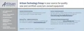
Figures 7-3, 7-4, and 7-5 show ideal (clean) waveforms and waveforms that may cause the
output to be inaccurate. Please consult the factory if the waveform you detect is not similar
in principle to these waveforms.
Figure 7-3. Clean Signals
A. Vortex signal (TP1)
B. Trigger level
C. Shedding frequency output
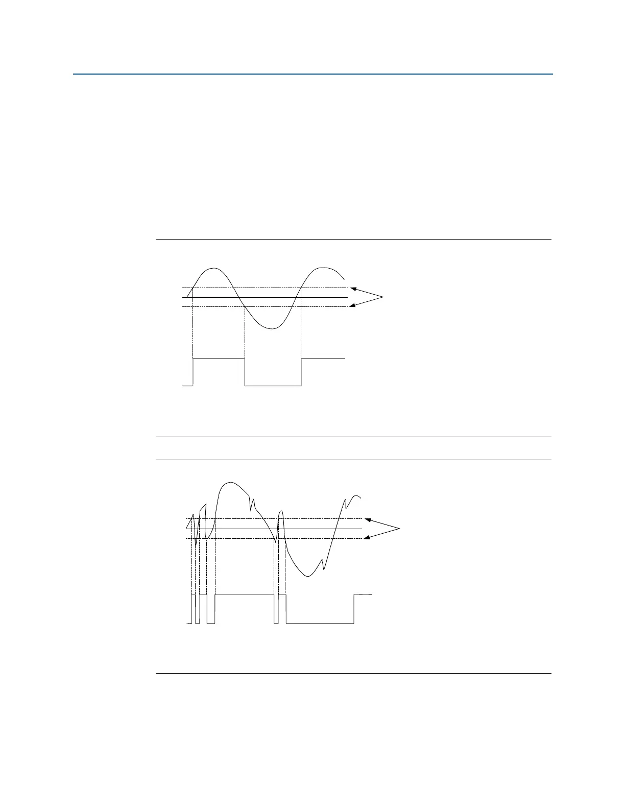
Figure 7-4. Noisy Signals
A. Vortex signal (TP1)
B. Trigger level
C. Shedding frequency output

 Loading...