28 Installation CG Drives & Automation 01-7491-01r0
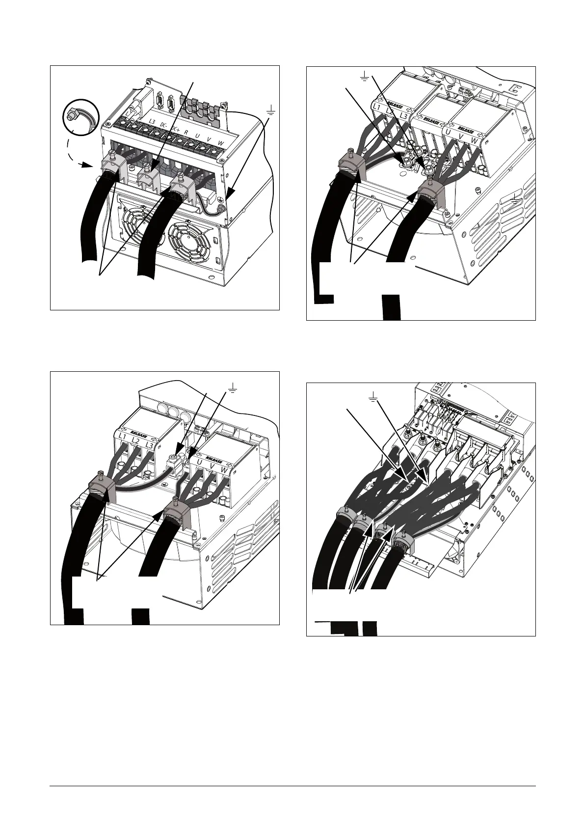
Fig. 36 Mains and motor connections model 48-072 to
48-105, frame size D2 and model 69-033 to 69-058
frame size D2(69).
Fig. 37 Mains and motor connections model 48-142 to 48-
293 (frame sizes E2 and F2) (principle drawing).
Fig. 38 Mains and motor connections model 48-142 to 48-
293 (frame sizes E2 and F2) with the optional termi-
nals for DC-, DC+ and Brake (principle drawing).
Fig. 39 Mains and motor connections model 48-365-20
(frame size FA2) with the optional terminals for DC-,
DC+ and Brake (principle drawing).
PE
M
a
i
n
s
M
o
t
o
r
for brake resistor
cables (option)
Strainrelief and EMC clamp
also for screen connection
of cables
Strainrelief and EMC clamp
PE
M
o
t
o
r
M
a
i
n
s
Strainrelief and EMC clamp
also for screen connection
of cables
PE
M
o
t
o
r
M
a
i
n
s
Strainrelief and EMC clamp
also for screen connection
of cables
PE
M
o
t
o
r
M
a
i
n
s
Strainrelief and EMC clamp
also for screen connection
of cables
M
a
i
n
s
M
o
t
o
r
M
o
t
o
r

 Loading...

